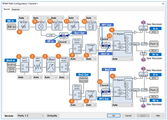
The path configurator allows you to configure hardware components that are available with the M9834A and M9837A PXIe.
How to access Path Configurator |
|
|
Using Hardkey/SoftTab/Softkey |
Using Menus: |
|
|
The connectors on the front panel is shown in the block diagram figure. See PXIe VNA Front Panel Tour.
M9837A-205 (There is the BB In connector on front panel. However, it is not available.)
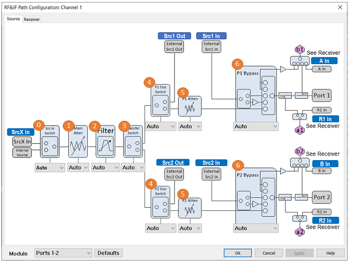
No. 7 to 13 are not available in the M9834A-205.
|
No. |
Name |
Selection |
Element Name |
Setting |
|
0 |
Src In Switch |
Auto: Set the switch automatically according to the application. Internal: Use internal source External: Use Src X In port input |
"Module<moduleNo>SourceIn" ex: "Module1SourcIn" |
"Auto", "Internal", "External" |
|
1 |
Main Atten |
Auto: Set the attenuator automatically according to the signal level. 0 dB to 60 dB, 2 dB step Note: Use Mixer Atten (No. 12) to adjust the signal level though Up-converter path over 20 GHz. |
"Module<moduleNo>SourceAttenuator" ex: "Module1SourceAttenuator" |
“Auto“, “0“, “2“, “4“, …, “60“ |
|
2 |
Source Filter |
Auto: Set the filter automatically according to the signal frequency. Filter 1 to Filter 10: See the table below. Bypass: No filter |
“Module<moduleNo>SourceFilter“ ex: "Module1SourceFilter" |
“Auto“, “Filter1”, “Filter2”, … “Filter10”, “Bypass” |
|
3 |
Transfer Switch |
Auto: Set the switch automatically according to the application and signal frequency.. The Port1 is selected over 20 GHz. See Source Path Block Diagram. All Off: Source is off. Recommended to turn off the state in Power and Attenuator Dialog when you want to turn off the source power. All On: Source output is both ports 1 and 2 paths Port 1: Source output is port 1 path Port 2: Source output is port 2 path. |
“Module<moduleNo>TransferSwitch“ ex: "Module1TransferSwitch" |
Auto“, “Port<n>“, “Port<n+1>“, “AllOn“, “AllOff“ Assigned port number should be used in the multi-port configuration. ex: Port3, Port4 |
|
4 |
P1 Out Switch/ P2 Out Switch |
Auto: Set the switch automatically according to the application and signal frequency. External : Source output is Src 1 (P1 Out) / 2 Out (P2 Out) Internal: Source output is P1/P2 Atten path |
“Port<portNo>SourceOut“ Assigned Port number should be used in the multi-port configuration. ex: "Port1SourceOut" |
“Auto“, “External“, “Internal" |
|
5 |
P1 Out Atten / P2 Out Atten |
Auto: Set the attenuator automatically according to the signal level. 0 dB to 30 dB, 2 dB step |
“Port<portNo>SourceAttenuator“ Assigned port number should be used in the multi-port configuration. ex: "Port1SourceAttenuator" |
“Auto“, “0“, “2“, “4“, “6“, … , “30“ |
|
6 |
P1 Bypass / P2 Bypass |
Auto: Set the switch automatically according to the application and signal frequency. Bypass 20 GHz: Bypass path (=< 20 GHz). Bypass path is available for test receivers (bx) only Bypass 44 GHz: Bypass path (>20 GHz). Bypass path is available for test receivers (bx) only. Bypass Auto: When the receiver frequency is greater than 20GHz, Bypass 44 GHz is selected. External Amp: Source from frequency converter through the amplifier External Thru: Source from frequency converter Internal: Internal Source |
“Port<portNo>SourceBypass“ Assigned port number should be used in the multi-port configuration. ex: "Port3SourceBypass" |
"Auto“, “Internal“, “ExternalThru“, “ExternalAmp“, “Bypass20GHz“, “Bypass44GHz“, “BypassAuto“ |
|
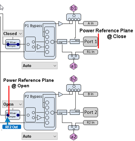
7 |
Src Jumper (Src1 Out to RF In)
|
Open: Select this if the jumper cable on the front panel is disconnected. The source level is defined at the port of Src1 Out. Need to set the P1 Out Switch at External. Close: Select this if the jumper cable on the front panel is connected. |
“Module<moduleNo>SourceJumper“ ex: "Module1SourceJumper" |
“Open“, “Closed“ |
|
8 |
BB Atten |
Auto: Set the attenuator automatically according to the signal level. 0 dB to 31.5 dB, 0.5 dB step (M9837A-205) BB In is not available. This selection is not displayed. |
“Module<moduleNo>BaseBandAttenuator“ ex: Module3BaseBandAttenuator |
“Auto“, “0“, “0.5“, “1“, “1.5“, …., “31“, “31.5“ |
|
9 |
RF Mixer |
Auto: Set the mixer path automatically according to the application. Baseband: BB In Path Mixer: Mixing BB In and RF signal from Src1 Out. RF: Src1 Out path (M9837A-205) BB In is displayed in the dialog box but it is not available. RF only |
“Module<moduleNo>SourceMode“ ex: Module1SourceMode |
“Auto“, “Baseband“, “Mixer“, “RF" |
|
10 |
Mixer Filter |
Auto: Set the filter automatically according to the signal frequency. Filter 1 to Filter 19 : See the table below. Bypass: No filter When RF Mixer is set at Baseband, AUTO is displayed and the filter behaves as Bypass because of hardware restriction. |
“Module<moduleNo>MixerFilter“ ex: "Module1MixerFilter" |
“Auto“, “Filter1“,… “Filter19“, “Bypass“ |
|
11 |
Mixer Atten |
Auto: Set the attenuator automatically according to the signal level. 0 dB to 90 dB, 5 dB step If RF Mixer is set to Baseband or Mixer, the attenuator can be set up to 75. |
“Module<moduleNo>MixerAttenuator“ ex: Module1MixerAttenuator |
“Auto“, “0“, “5“, “10“, …, “90“ If ModuleSourceMode is set to Baseband or Mixer, if the value is larger than 75, the actual attenuator setting is 75. |
|
12 |
Mixer Switch |
Auto: Set the switch automatically according to the application. All Off: Source is off All On: Source output is both ports 1 and 2 paths Port 1: Source output is port 1 path Port 2: Source output is port 2 path. |
“Module<moduleNo>MixerTransferSwitch“ ex: Module3MixerTransferSwitch |
Auto“, “Port<n>“, “Port<n+1>“, “AllOn“, “AllOff“ Assigned port number should be used in the multi-port configuration. ex: Port3, Port4 |
|
13 |
Mixer P1 Jumper (RF1 Out to Src1 In) Mixer P2 Jumper (RF2 Out to Src2 In) |
Open: Select this if the jumper cable on the front panel are disconnected. The source level is defined at the port of RF1 Out and RF2 Out. Close: Select this if the jumper cable on the front panel are connected. |
"Port<portNo>SourceMixerJumper“ Assigned port number should be used in the multi-port configuration. ex: "Port2SourceMixerJumper"
|
“Open“, “Closed“ Power reference plain is changed as below. Open: RF1/2 Out, Close: Test Port 1/2
|
Source Filter “Module<moduleNo>SourceFilter“
Note: If you observe the filter shape directly at the receiver, the shape of measurement result looks like a Low pass filter. However, it is optimized to produce the characteristic in the range of table above. |
Mixer Filter “Module<moduleNo>MixerFilter“
|
The M9837A uses the up-converter path over 20 GHz frequency. The red line shows the port 1 source path. The dotted yellow line shows the port 2 source path.
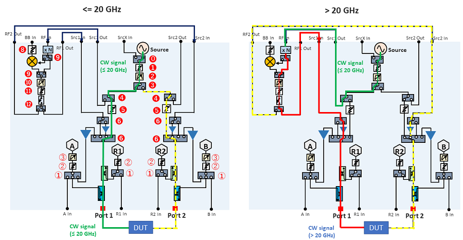
The connectors on the front panel is shown in the figure.
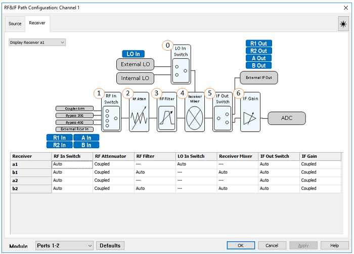
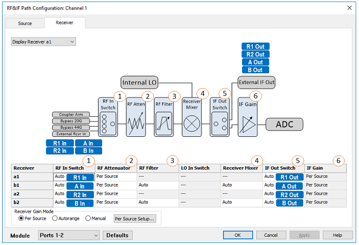

|
No. |
Name |
Selection |
Element Name |
Setting |
|
0 |
LO In Switch |
This is global setting for all receivers. If "External" is set for either module and Sweep Mode is set at "Auto", internal sweep mode is fixed to the Stepped Sweep. Auto: The optimal setting is selected internally according to the module configuration. External:Use the external LO signal from LO In on the front panel. Internal:Internal LO is used. |
“Module<moduleNo>LOSource“ ex: “Module2LOSource“ |
“Auto“, “Internal“, “External“ |
|
1 |
RF In Switch |
Auto: Set the switch automatically according to the application. Internal: Coupler path External: R1 In (a[n]), R2 In (a[n+1]), A In (b[n]), B In (b[n+1])) Bypass 20 GHz: Bypass path (=< 20 GHz). Bypass path is available for test receivers (bx) only. Bypass 44 GHz: Bypass path (>20 GHz). Bypass path is available for test receivers (bx) only. Bypass Auto:The receiver frequency is equal to or less than 20 GHz- Bypass 20 GHz, The receiver frequency is grater than 20 GHz- Bypass 44 GHz |
“ReceiverBypass<recieverNotation> ex) ReceiverBypassa1, ReceiverBypassb3 |
“Auto“, “Internal“, “External“ Test receivers (bx) only: "Bypass20GHz", "Bypass44GHz", "BypassAuto" |
|
2 |
RF Atten |
Coupled: Gain Coupling in Receiver Gain is checked. (Same as IF Gain) 0 dB to 30 dB, 2 dB step (When Gain Coupling is disabled) Note: Receiver Gain in pull down menu shows Receiver Gain dialog box. |
RFAtten value is controlled by the following SCPI commands: SENSe:SOURce:RECeiver:GAIN:COUPling:ALL[:VALue] changes the ‘Gain Coupling’ setting. |
|
|
3 |
RF Filter |
RF Filter selection is available only for test receivers (bx) Auto: Bypass is selected Filter 1 to Filter 13 : See the table below. Bypass: No filter Filtered : Select the filter automatically according to the measurement frequency. |
“Port<portNo>ReceiverFilter“ Assigned port number should be used in the multi-port configuration. ex: "Port1ReceiverFilter" |
“Auto“, “Filter1“, “Filter2“, … , “filter13“, “Bypass“, “Filtered“ |
|
4 |
Receiver Mixer |
Receiver Mixer selection is available only for test receivers (bx) Auto: Set the mixer path automatically according to the application. Mixer: Mixer PassThru: Mixer is not used. |
"Port<portNo>Mixer“ Assigned port number should be used in the multi-port configuration. ex: Port3Mixer |
“Auto“, “PassThru“, “Mixer“ |
|
5 |
IF Out Switch |
Auto: Set the switch automatically according to the application. Internal: Internal IF is used. External: Output the signal to R1 Out (a[n]), R2 Out (a[n+1]), A Out (b[n]), B Out (b[n+1]) on the front panel. |
“IFSwitch <recieverNotation> ex) IFSwitcha1,IFSwitchb3 |
“Auto“, “Internal“, “External“ |
|
6 |
IF Gain |
Coupled: Gain Coupling in Receiver Gain is checked. (Same as RF Atten) Auto: Set the gain automatically according to the signal level. (When Gain Coupling is disabled) 6 dB to 26 dB, 2 dB step (When Gain Coupling is disabled) Note: Receiver Gain in pull down menu shows Receiver Gain dialog box. |
“IFGain<recieverNotation> ex) IFGaina1,IFGainb3 |
“Auto“, “6“, “8“, “10“, “12“, …, “26“
Note: SENSe:SOURce:RECeiver:GAIN:COUPling:ALL[:VALue] changes the ‘Gain Coupling’ setting.
|
Receiver Gain Mode: See Receiver Gain
|
Filter No. |
Lower |
Upper |
|
Filter 1 |
|
470 MHz |
|
Filter 2 |
470 MHz |
760 MHz |
|
Filter 3 |
760 MHz |
1.2495 GHz |
|
Filter 4 |
1.2495 GHz |
1.98 GHz |
|
Filter 5 |
1.98 GHz |
2.8 GHz |
|
Filter 6 |
2.8 GHz |
4.1 GHz |
|
Filter 7 |
4.1 GHz |
6.13 GHz |
|
Filter 8 |
6.13 GHz |
9 GHz |
|
Filter 9 |
9 GHz |
12.2 GHz |
|
Filter 10 |
12.2 GHz |
18 GHz |
|
Filter 11 |
18 GHz |
22.6 GHz |
|
Filter 12 |
22.6 GHz |
30 GHz |
|
Filter 13 |
30 GHz |
44 GHz |