Single Channel GPS Source
This section is only applicable to the lab application or test application with the required feature license.
Description
The Single Channel GPS Source function allows you to generate GPS signals to calibrate the GPS receiver of the mobile.
GPS system employs 37 satellites in orbit to provide positioning services. Satellite GPS signal has 3 components: L1 (1575.42MHz) / L2 (1227.60MHz) carrier signals, ranging codes and navigation message. Two kinds of ranging codes are defined: coarse/acquisition (C/A) code for normal positioning and precision (P) code for finer positioning purpose. The L1 is used to carry the C/A code with 1.023Mcps spreading rate, while L2 is usually used to carry the P code with 10.23Mcps spreading rate. For each satellite, a unique Space Vehicle Identifier (SV-ID) is assigned and will be used to determine the phase of spreading code for this specific satellite. The navigation messages usually contain positioning parameters.
Normally P code and L2 are only designed for military use, so the test set only simulates single satellite signal containing C/A code carried by L1 with default navigation messages, and pseudo random sequence data for the calibration of GPS receivers.
GPS Info
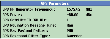
The following diagram shows the GPS parameter information.

-
GPS RF Generator Frequency:
Since the test set only simulates single satellite signal containing C/A code carried by L1, the frequency is fixed at 1575.42MHz. It's a non-configurable parameter.
-
GPS Power:
This parameter defines the cell power of GPS signal. The power range of GPS signal is -125dBm to -70dBm.
The power range that you can set on the test set is affected when there is an Amplitude Offset.NOTE
GPS Satellite ID (SV ID):
This setting defines which satellite is generating the GPS signal.
GPS Navigation Message Type:
This setting defines the actual navigation message that will be transmitted on GPS frame. If Default Navigation is selected, the GPS frames is filled with the default navigation message defined in the GPS standard. If Raw is selected, the GPS frames is filled with PN sequence.
GPS Raw Payload Pattern:
This setting defines the data type that will be transmitted on GPS frames when Raw data payload is selected. You can select PN9 or PN15.
GPS Baseband Filter Type:
This setting defines the filter that will be used to filter the GPS baseband signal when the GPS signal is generated. A Gaussian or Rectangle filter with 10 MHz bandwidth is supported in this feature.
GPS Parameters
The following table lists all the configurable GPS parameters.
RF Gen Configure GPS Power GPS Power State GPS Power & State GPS Satellite ID (SV ID) GPS Navigation Message Type GPS Raw Payload Pattern GPS Baseband Filter Type GPS RF Generator Frequency GPS RF Generator Frequency 2