CW Operating Mode
Description
When in CW operating mode, the test set operates like a signal generator. The basic features provided by CW operating mode are:
- No over the air signaling is used. Therefore there is no synchronization between the mobile station and test set.
- No demodulation or channel decoding is available.
-
No automatic receiver control is provided. Expected CW power, measurement receiver frequency, and uplink receiver frequency are available as manual settings only.
Manual receiver control settings made while using the CW operating mode can affect manual receiver settings made in other operating modes. When changing operating modes and using manual receiver settings, always verify that the manual receiver settings are correct for the new operating mode.
- Any one of three test signals can be generated while analyzing another signal (at the same frequency or at a different frequency). No interaction exists between these controls.
- All test set measurements are available while in CW operating mode. However, measurements requiring protocol triggering cannot be made. Immediate triggering should be used for most measurements because no overhead signaling is occurring. Protocol triggering will timeout or report an integrity indicator other than zero.
Test Signals Description
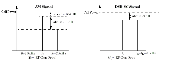
The test set in CW operating mode provides any one of three test signals: CW (no modulation), AM (fixed 56% amplitude modulation), and DSB-SC (dual side-band suppressed carrier). An example usage of the test signals is for calibrating mobile stations that use Qualcomm's radioOne™ Zero Intermediate Frequency (Zero IF) architecture.
You can select any one of three signals with adjustable power level and frequency for output to the currently selected front panel RF connector.
- With CW test signal selected (the default setting), the test set provides an unmodulated carrier. With either AM or DSB-SC test signal selected, the test set will modulate the signal as shown in the following figure.
-
For any of the test signals selected, the output power level is controlled by the
Cell Power( F7 ). The Cell Power refers to the power found in the entire signal including sidebands if applicable. -
For any of the test signals selected, the frequency is adjusted by changing the
RF Gen Freq( F8 ).- With the CW or AM signal selected, the RF Gen Freq setting represents the center frequency of the signal (fc).
- With the DSB-SC signal selected, the RF Gen Freq setting represents the frequency of the lower sideband signal (fL). The upper sideband (fh) is 20 kHz above the RF Gen Freq setting, that is fh = fL+20 kHz.

Programming Usage
Use the following commands to control each function for CW operating mode:
- Select CW operating mode: CALL[:CELL]:OPERating:MODE
- Set the cell power output level to be transmitted by the test set: CALL:POWer
- Set the RF generator frequency: CALL[:CELL]:RFGenerator:FREQuency
- Set the expected CW power level to be received by the test set: RFANalyzer:CW:EXPected:POWer
- Set the measurement receiver frequency: RFANalyzer:MANual:MEASurement[:MFRequency]