Polatis 6000 Switch
Avoid damaging the inputs of DCA-M modules. The front panel of many optical switches list the maximum power above which the switch is damaged. Be aware that the switch's maximum power level may far exceed the maximum safe power limits to DCA-M module inputs. Never exceed the maximum power level shown on the DCA-M module's front panel.
Example Polatis Switch IDs
Because Polatis offers many configurations of installed switch modules, your switch may not match this picture. The following picture shows how the Polatis switch ports are named. The ID string for a port is simply an integer.
| Front Panel | ||
|---|---|---|

|
||
| Switch Ports | ||
| Front Panel Label | Out (Ports 25 through 48) |
In (Ports 1 through 24) |
| Port Function in FlexOTO | Inputs From | Outputs To |
| DCA-M Modules | ● | |
| Fixtures | ● | |
| Demultiplexers | ● | ● |
| Impairments | ● | ● |
| User Instruments | ● | |
| Color definitions in table: | ||
| Switch ports that FlexOTO considers to be switch inputs. | ||
| Switch ports that FlexOTO considers to be switch ouputs. | ||
Switch drawings are representative examples as switch models often come in different configurations. FlexOTO supports other module/switch configurations that are not shown. The basic concepts still apply.
The number of fixtures tested, lane counts, and DCA-M channels all consume available switch ports. In the Available Port Connections table above, equipment shown as available may in fact be unavailable due to situations in which all available ports are already assigned. In these situations, you may be able to free up switch ports by using only one DCA-M channel or deleting a user instrument, impairment, or multiple fixtures. Of course, switches with more ports provide more flexibility.
Example Setup
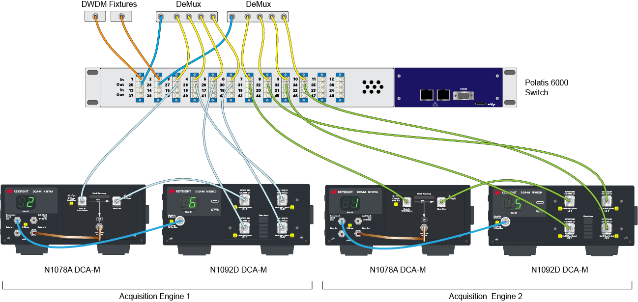
This example shows a DWDM Fixture being tested using a Polatis Series 6000 24 x 24 switch. Two acquisition engines are configured using N1078A clock recovery modules and N1092D four channel oscilloscopes. Test times are primarily be affected by the number of DCA-M acquisition / analysis engines in the test setup.
Fiber optic cable colors do not imply any fiber function but simply help make the cable paths easier to see in the drawing.
On Polatis Series 6000 switches, FlexOTO uses reverse port direction. For example, Fixture outputs are connected to switch ports that are labeled as Out on the switch's front panel. DCA-M inputs are connected to switch ports that are labeled as In on the switch's front panel.

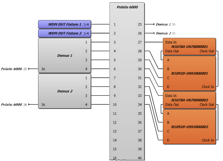
The following picture matches the setup equipment connections shown in the above picture.
