2. Model the Test Station in FlexOTO
When you first open FlexOTO, the Hardware Diagram![]() A FlexOTO pane where one models (draws) fiber-optic connections between test setup hardware blocks. pane is displayed. The Hardware Diagram is where you model the physical layout of your Test Station
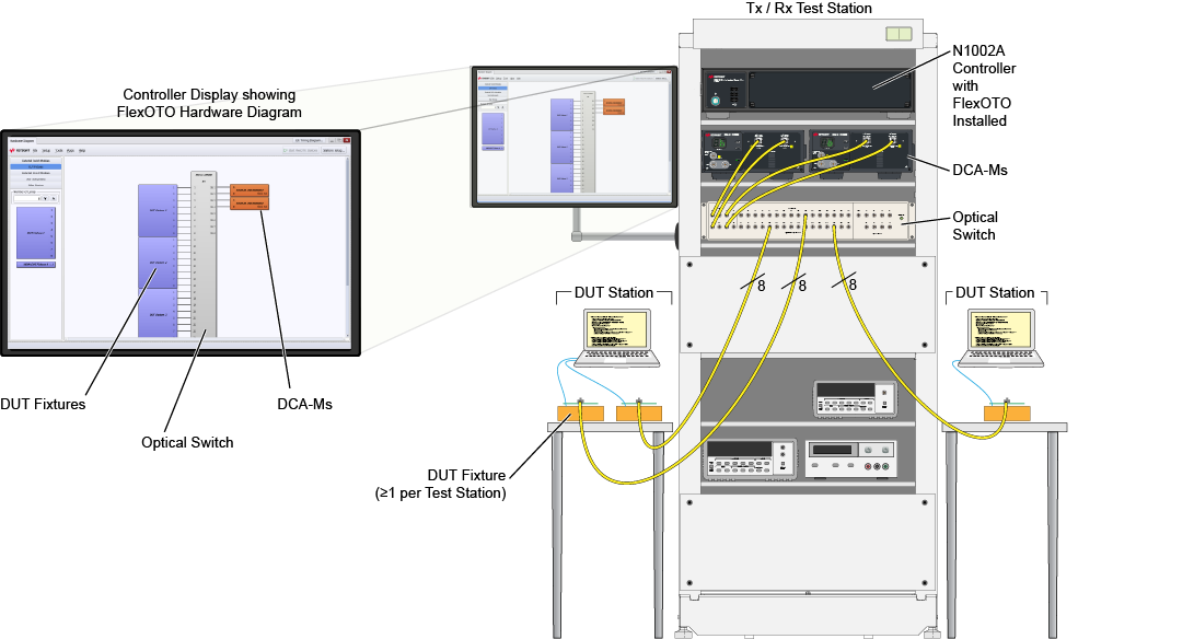
A FlexOTO pane where one models (draws) fiber-optic connections between test setup hardware blocks. pane is displayed. The Hardware Diagram is where you model the physical layout of your Test Station![]() A manufacturing setup for testing one or more DUT Fixtures. The Test Station includes a Text Executive program to control DUT settings and temperature. so that FlexOTO knows how to control the optical switch routes and DCA-Ms.
A manufacturing setup for testing one or more DUT Fixtures. The Test Station includes a Text Executive program to control DUT settings and temperature. so that FlexOTO knows how to control the optical switch routes and DCA-Ms.
This drawing shows only 3 Test Stations but you can define up to 16! The drawing also shows one switch model and two DCA-M modules. But, you can select from many supported auto-detected equipment.
If your optical switch is not supported, you can write your own optical switch driver to enable FlexOTO to control the switch. This is explained in FlexOTO's Programmer's help.