7. Hardware Diagram Rules
Please keep these general requirements and tips in mind as you learn about FlexOTO.
All DUT Fixtures Must Have the Same Lane Count
In FlexOTO, all DUT Fixtures in your Test Station![]() A manufacturing setup for testing one or more DUT Fixtures. The Test Station includes a Text Executive program to control DUT settings and temperature. and Hardware Diagram
A manufacturing setup for testing one or more DUT Fixtures. The Test Station includes a Text Executive program to control DUT settings and temperature. and Hardware Diagram![]() A FlexOTO pane where one models (draws) fiber-optic connections between test setup hardware blocks. must have the same number of lanes. Enter the number of lanes in the DUT Fixtures tab on FlexOTO Hardware Diagram
A FlexOTO pane where one models (draws) fiber-optic connections between test setup hardware blocks. must have the same number of lanes. Enter the number of lanes in the DUT Fixtures tab on FlexOTO Hardware Diagram![]() FlexOTO's switch diagram pane for modeling the test environment's physical hardware. (
FlexOTO's switch diagram pane for modeling the test environment's physical hardware. (:CONFigure:NLANes command).
All DCA-Ms Scopes Use the Same Number of Channels in FlexOTO
When multiple DCA-M oscilloscopes are installed, FlexOTO only uses the input channels that exist on all of the DCA-M modules on the switch diagram. For example, the following picture shows an N1092A with Channel A and an N1092D with four channels: A, B, C, and D. FlexOTO will only use channel A on the N1092D. Channels B, C, and D will not be used. If a two channel N1092B were substituted for the N1092A, the N1092D's A and B channels would become available.
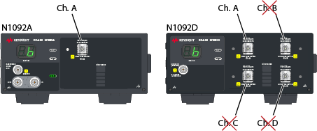
The Number of FlexOTO Stations Must be ≤ Number of DUT Fixtures
- Each FlexOTO Station
 A FlexOTO child process for making independent measurements for a Test Station. must have one or more DUT Fixtures assigned to the session.
 - A DUT Fixture cannot be assigned to multiple Stations.
DUT Fixtures are Assigned to Stations
Use the Measurement Station Setup dialog to specify the number of Stations used. To open the dialog, click Station Setup located above the Hardware Diagram. The basic rules for creating valid Station-to-Fixture assignments, are illustrated on FlexOTO's assignment chart.
Unassigned sessions are not allowed and will cause the Hardware Diagram to be invalid as
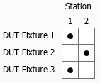
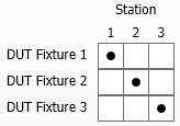
The following charts replicate those in the Measurement Station Setup dialog and show what assignments are permissible. Most of the time, you'll assign each Fixture to its own Station. However, multiple Fixtures can be assigned to the same Station.
| Invalid Chart (Unassigned Stations) |
Valid Chart |
|---|---|
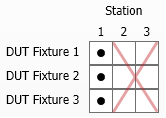
|
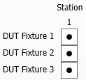
|
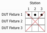
However, you cannot assign a fixture to multiple Stations. As shown in the following chart, after Station 1 was assigned to Fixture 1, Fixtures 2 and 3 cannot be added. Three correct charts are shown out of many possible configurations.
| Invalid Chart (Fixture in Multiple Stations) |
Valid Charts | ||
|---|---|---|---|
|

|
|
|
Switch Input and Output Ports
Many optical switches have more ports labeled as outputs than inputs. However, FlexOTO setups benefit from more input than output ports. In these cases, FlexOTO swaps the use of the switch's ports. For example, you would connect the output of your DUT Fixture to a port labeled as an output port on the switch's front panel. On the Hardware Diagram:
- FlexOTO prevents Invalid switch connections and will not allow you to create Test Programs until the valid ports are used.
- Model your connections first on the Hardware Diagram and then make the actual fiber optical cable connections between the ports as indicated on your the Hardware Diagram.
