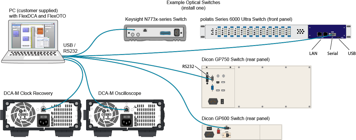
Step 1. Connect Switch and DCA-Ms
FlexOTO Instance:
Hardware Diagram
Stations
- Start the FlexOTO application.
- Apply power to your optical switch and to the DCA-M modules that you plan to use. Do not connect any USB/RS232 cables at this time. Only one optical switch can be used. The optical switch and DCA-M modules must be recognized by FlexOTO. If your optical switch is not recognized, you can write your own optical switch driver.
- Allow time for the optical switch and DCA-Ms to boot up before proceeding to the next step.
- Connect the USB/RS232 cables for the optical switch and DCA-Ms to the PC where FlexOTO is running.
- FlexOTO automatically detects the optical switch and DCA-M modules via the LAN, USB, or RS-232 connections. In the unlikely event that FlexOTO does not detect a switch or DCA-M, you can open the FlexDCA application and manually establish the connections using FlexDCA's Extended Module Configuration dialog. Confirm that the optical switch and DCA-Ms have been automatically installed as extended modules. A Switch slot tile (and DCA-M tile) should be displayed in along FlexDCA's bottom tray.
- Turn on each DUT Fixture that you will use in your setup.
- Optional steps:
- Use a patch cord to connect one DUT Fixture output directly to your DCA-M modules.
- Open the FlexDCA application, and configure your DCA-M modules settings so that the DCA-M oscilloscope can trigger on and view the signal.
- Remove the patch cord.
- Return to FlexOTO.
- Continue with Step 2. Build the Hardware Diagram.

