Step 2. Build the Hardware Diagram
FlexOTO does not allow invalid Hardware Diagram connections. Because of the Hardware Diagram's guided setup, it is recommended that you always connect all the ports on the Hardware Diagram before connecting the actual physical fiber optic cables in your test setup.
- Start FlexOTO which automatically detects supported DCA-M modules as well as a recognized switch (by default).
- If you plan to remotely operate FlexOTO, turn on FlexOTO's SCPI Recorder so that you can capture and view FlexOTO Hardware Diagram SCPI commands as you configure the Hardware Diagram. The SCPI Recorder quickly lists the commands you will need. Click Tools > SCPI Programming Tools > SCPI Recorder.
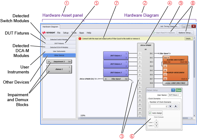
- FlexOTO has two panels: Hardware Asset Panel 1 and the Hardware Diagram 2 as shown in the following picture.
- Click on the DUT Fixtures panel 5 and enter the number lanes that your DUT Fixtures have.
- Drag hardware blocks, for example the switch 4, from the Hardware Assets panel to the Hardware Diagram.
- Make port connections on the Hardware Diagram by clicking a hardware block's port and then clicking the desired port on the Switch or other hardware block. This is shown as item 3 in the above figure.
- If a placed DUT or WDM DUT fixture has multiple clock domains, click on the Fixture block to open the Fixture Setup dialog 6 where you can assign the clock domains to different lanes.
- Click Stations Setup 8 to open the FlexOTO Stations Setup dialog. Select the number of Stations that you have. If Stations have multiple DUTs, assign the DUT Fixtures to your Stations. The Wavelength selection in this dialog selects FlexDCA's wavelength setting. If you want to select the wavelength setting of a Switch (if this setting exists for your switch), click on the Switch block.
- After modeling your setup and messages no longer appear above the Hardware Diagram 7, click Start FlexOTO Stations which is next to the Stations Setup button. FlexOTO Hardware Diagram then creates and starts the number of child processes, represented by Stations tabs in the GUI, that you have specified.
- Click on each Station tab, and configure your Station Test Plans.
- When you've completed running your Test Plan, click Job Timing Diagram 9. This displays a diagram where you can compare timing between User Stations or Task Breakdown.
- Continue with Step 3. Create and Run Test Plans.

The goal is to have the Hardware Diagram model your actual test setup including DUTs, DCA-Ms, demultiplexers, impairments, instruments, and switch connections.
Press the keyboard's SHIFT key while dragging blocks onto the Hardware Diagram and FlexOTO automatically make the necessary switch connections. You can easily change them if you want.
When you click a port on a hardware block or Switch, all possible valid connections are highlighted. Select the highlighted port that matches your test setup.
When you click on placed hardware blocks other than switch and DCA-M modules, a dialog 6 opens that allows you to enter a custom name for the block and may also include other options.
| Hardware Block | Switch's Side | Setup Dialog | |
|---|---|---|---|
| Switch Input | Switch Output | ||
| DUT Fixture | ● | ● | |
| WDM DUT Fixture | ● | ● | |
| DCA-M Modules | ● | — | |
| Demultiplexer | ● | ● | ● |
| Impairment | ● | ● | ● |
| Instrument | ● | ● | |
Alert messages appear above the Hardware Diagram to alert you to errors that invalidate a diagram. FlexOTO will not let you begin testing if your Hardware Diagram has an alert.
The Start FlexOTO Stations button changes to Stop FlexOTO Stations which you can click at any time to end all running Stations.