Dynamic Accuracy — Factory Recommended Variant

Equipment and Setups

This test applies to the following models using the Factory Recommended Variant test plan:

This test is extremely sensitive. To minimize the chance of test failure, it is important to follow proper testing procedures:

  • On the PNA, go to Utility > System > System Setup > Preferences. Ensure that this setting is NOT selected: Marker: Coupling controls on/off state of markers.
  • Ensure all connectors are clean.
  • Properly torque all connections.
  • Check that all test equipment is attached to the correct connecter and has solid connections.
  • Ensure that the required equipment is being used.
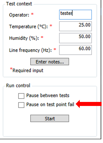
  • Be sure that ClosedPause on test point fail is not selected for this test.


This topic shows the required equipment and connection setups for PNA models running the Factory Recommended Variant test plan. For more information about test plan variants, refer to the Test Plan Variants topic.

For models with Low Frequency Extension option (LFE), there is an additional test procedure. Refer to the Dynamic Accuracy at Low Frequency topic page.

Required Test Equipment

For PNA mmWave Systems N5290A and N5291A.

1 mm Connector Models

Test Equipment1

Recommended Model

Function generator

33622A

Power splitter

11667B

Fixed attenuator, 10 dB
(2 required)

8493C Option 010

  1. Refer to the main test equipment table for available cables and adapters listed by connector type.


For all other PNA models.

Test Equipment1

Recommended Model

Alternate Model

Power meter
(PowerMeter1)

N1914B

N1914A
E4419A/B
N1912A

PowerSensor 1, for 3.5 mm models

U8485A2 Opt. 200

U8485A2
N8485A3

PowerSensor 1, for 2.4 mm models

U8488A2

U8487A2
N8488A3

PowerSensor 1, for 1.85 mm models

U8488A2

N8488A3

Dynamic Accuracy test set4
(DynAcc TestSet2)

U3020BD01

U3020AD01

Signal Generator
(SignalGenerator1)

E8257D

N5183B
N5182B

E8257C
E8267C/D

E8247C (not allowed for N5241x and N5242x PNA-X)

Load, 3.5 mm 50 W

909D

902C

  1. Refer to the main Required Equipment table for a list of available adapters and cables.
  2. Requires power meter with USB ports.
  3. Not allowed with models with Low Frequency Extension (LFE) options.

Connection Setups

Due to the complexity of the PNA family of analyzers, the following notes apply to illustrations in the PNA Help:

  • Only a single representative PNA model will be shown. Therefore, port locations may differ in older PNA models than what is shown in the illustration. Refer to the port labels on the UUT.
  • Some illustrations may differ than those in TME.
  • If the test procedure applies to multiple ports, illustrations may show the setup on only one test port.
  • Setups for some option configurations may not appear in the Help.

Flexible power sensor channel assignment

PNA models running the Factory Recommend Variant will use flexible power sensor channel assignment that will identify the channel that a power sensor is connected to using the ability of "smart" sensors such as the N848xA and U848xA series to report their full model and serial number. Therefore it is important to keep the power sensor on the channel where it was calibrated throughout the test procedures.

For more information about test plan variants, refer to the Test Plan Variants topic.

Power Sensor Calibration Setup