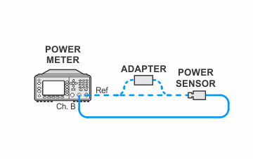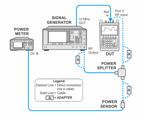
All adjustments will require the CFG Option. Refer to the CFG Option section for more information.
N9935A/36A/37A/38A
|
|
All adjustments will require the CFG Option. Refer to the CFG Option section for more information. |
The SA calibration consists of five different adjustments that should be performed in succession in the following order. For more information, click here.
This procedure characterizes the hardware IF filter and stores the characterization information in the FieldFox. A characterization is performed for each SA band. The characterization information is used to improve measurement accuracy when post-processing the raw measurement data.
|
Related test: |
|
Test Equipment |
Recommended Model Number |
|---|---|
|
Signal Generator #1 |
E8257D with options:
.) |
|
Power Meter |
N1914A |
|
Power Sensor |
E9304A Opt H20 |
|
Power Sensor |
N8485A |
|
Power Splitter, 3.5 mm |
11667B |
|
Power Sensor Cable |
11730A |
|
BNC Cable |
8120-2582 |
|
Coaxial Cable |
11500E |
|
Adapter, 3.5 mm (m) to Type-N (m) |
1250-1743 |
|
Adapter, 3.5 mm (f) to 3.5 mm (f) |
83059B |
|
Adapter, 2.4 mm (f) to 3.5 mm (f) |
11901B |
|
Adapter, 3.5 mm (f) to Type-N (m) |
08485-60005 |
|
|
The following notes apply to illustrations in the FieldFox Help:
|


