All adjustments will require the CFG Option. Refer to the CFG Option section for more information.
N9935A/36A/37A/38A
|
|
All adjustments will require the CFG Option. Refer to the CFG Option section for more information. |
The SA calibration consists of five different adjustments that should be performed in succession in the following order. For more information, click here.
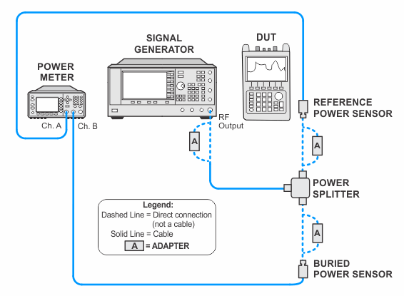
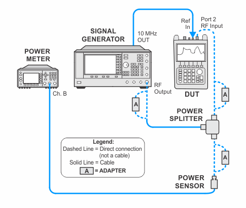
The preamp OFF frequency response adjustment is performed with 10 dB RF attenuation. The preamp On frequency response adjustment is performed with 20 dB RF attenuation. In these procedures, numbers of frequencies are adjusted in each band by measuring the difference between the power sensor measurement and the DUT measurement for each target frequency. Each band has a unique CAL file number and frequencies within that band will be stored only in that CAL file using frequency and magnitude pair.
This adjustment generates the calibration factors for the internal source used in the InstAlign functionality.
|
Related tests: |
Total Abs Amp Accy Low Frequency |
|
Test Equipment |
Recommended Model Number |
|---|---|
|
Signal Generator #1 |
E8257D with options:
|
|
Power Meter |
N1914A |
|
Power Sensor |
E9304A Opt H20 |
|
Power Sensor |
N8485A |
|
Power Sensor |
8485D |
|
Attenuator, 30 dB |
11708A |
|
Power Splitter, 3.5 mm |
11667B |
|
Power Sensor Cable |
11730A |
|
BNC Cable |
8120-2582 |
|
Coaxial Cable |
11500E |
|
Adapter, 3.5 mm (m) to Type-N (m) |
1250-1743 |
|
Adapter, 3.5 mm (f) to 3.5 mm (f) |
83059B |
|
Adapter, 2.4 mm (f) to 3.5 mm(f) |
11901B |
|
|
|
|
|
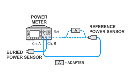
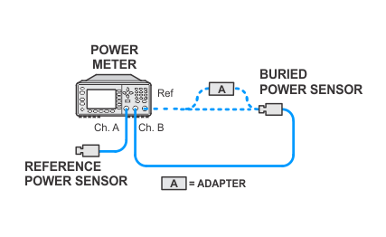
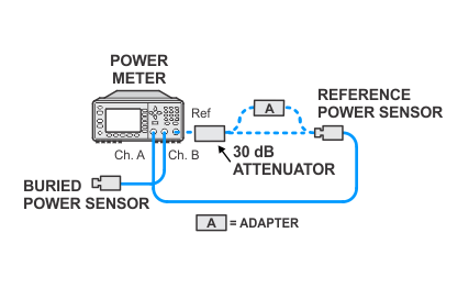
The following notes apply to illustrations in the FieldFox Help:
|
