In all test equipment configurations, cables and adapters must be properly torqued. Exceeding recommended torque values can cause damage to a cable or adapter, and can cause inaccurate test results.
This section lists the test equipment needed to run performance tests and adjustments. Refer to each individual test for specific setup configurations with required cables and adapters. Not all of the listed test equipment needs to be connected to perform an individual test. To run a test, only the equipment specified for that test needs to be connected.
|
|
In all test equipment configurations, cables and adapters must be properly torqued. Exceeding recommended torque values can cause damage to a cable or adapter, and can cause inaccurate test results. |
|
To make this connection |
Use this torque wrench and torque value |
Option 504 |
Option 518 |
Option 526 |
Option 550 |
|
2.4 mm (m) to 2.4 mm (f) |
8710-1765 |
X |
X |
X |
X |
|
3.5 mm (m) to 3.5 mm (f) |
8710-1764 |
|
|
X |
|
|
Type-N (m) to Type-N (f) |
8710-1766 |
X |
X |
|
|
|
|
|
|
Instrument |
Recommended Model Number |
Alternative Model Number |
|
Signal Sources |
||
|
Signal Generator |
E8257D
Option 1EU (or 1EA) |
|
|
Function Generator |
33622A |
33250A |
|
Power Supply |
E3632A |
|
|
Network Analyzer |
||
|
PNA Network Analyzer |
N5247B |
N5247A/AS E8361C E8364B |
|
ENA Network
Analyzer |
E5071C2 |
|
|
Meters |
||
|
Power Meter |
N1914B Option H505 |
N1914A Option H503, 4, 5 |
|
Power
Sensor |
N8482A Opt STD or CFT |
8482A |
|
Power
Sensor |
N8481A Opt STD or CFT |
8481A |
|
Power
Sensor |
N8485A Opt STD or CFT |
8485A |
|
Power
Sensor |
N8487A Opt STD or CFT |
8487A |
|
Attenuators |
||
|
3 dB Fixed Attenuator |
8491A Option 003 |
8491B Option 003 |
|
6 dB Fixed Attenuator |
8491A Option 006 |
8491B Option 006 |
|
1 dB Step Attenuator |
8494G |
|
|
10 dB Step Attenuator |
8496G |
|
|
Terminations |
||
|
50W Termination, 3.5 mm |
902D |
909D |
|
50W Termination, 2.4 mm |
901D |
85138B |
|
Miscellaneous Devices |
||
|
Amplifier |
Mini Circuit ZHL-1-2W-N |
|
|
Directional Coupler |
Pulsar Microwave Corporation C4-P4-411 |
|
|
Directional Bridge |
86205A |
|
|
Attenuator/Switch Driver |
11713B |
11713A |
|
Power Splitters |
||
|
Splitter, Type-N |
11667A Option H86 |
|
|
Splitter, 3.5 mm |
11667B Option H86 |
|
|
Splitter, 2.4 mm |
11667C Option H86 |
|
|
Mechanical Calibration Kits |
||
|
50W Calibration Kit, Type-N, 18 GHz |
85054B |
|
|
50W Calibration Kit, Type-N, 9 GHz |
85032F |
|
|
50W Calibration Kit, 3.5 mm, 26.5 GHz |
85052B |
|
|
50W Calibration Kit, 2.4 mm, 50 GHz |
85056A |
|
|
ECal Cal Kits |
||
|
50W Calibration Kit, Type-N, 18 GHz |
N4690D-M0F |
N4690B-M0F |
|
50W Calibration Kit, 3.5 mm, 26.5 GHz |
N4691D-M0F |
N4691B-M0F Or N4691BH33-M0F |
|
50W Calibration Kit, 2.4 mm, 50 GHz |
N4693D-M0F |
N4693A-M0F |
|
Cables |
||
|
Type-N
(m to m) |
11500C |
|
|
3.5 mm RF |
11500E |
8120-4921 |
|
2.4 mm RF |
8120-6164 |
|
|
Wire (from power supply to amplifier) |
|
|
|
Filters |
||
|
50 MHz Filter |
RLC
Electronics |
Low Pass Filter 0955-0306 |
|
Adapters |
||
|
Type-N (m) to 3.5 mm (f) |
1250-1744 |
|
|
BNC (m) to Type-N (m) |
1250-1473 |
|
|
3.5 (f) to Type-N (f) |
1250-1745 |
|
|
BNC (f) to Type-N (f) |
1250-1474 |
|
|
Type-N (f) to 3.5 mm (f) |
1250-1745 |
|
|
Type-N (f) to BNC (m) |
1250-1477 |
|
|
Type-N (m) to Type-N (m) |
85032-60019 |
|
|
2.4 mm (m) to 2.4 mm (m) |
11900A |
|
|
2.4 mm (f) to 3.5 mm (f) |
11901B |
|
|
2.4 mm (f) to 3.5 mm (m) |
11901D |
|
|
2.4 mm (f) to Type-N (f) |
11903B |
|
|
2.4 mm (f) to Type-N (m) |
11903D |
|
|
3.5 mm (f) to Type-N (m)9 |
08485-60005 |
|
|
2.4 mm (f) to Type-N (m)9 |
08487-60001 |
|
|
Optional Equipment |
||
|
Verification Kit, Type-N10 |
85055A |
|
|
Verification Kit, 3.5 mm10 |
85053B |
|
|
Verification Kit, 2.4 mm10 |
85057B |
|
Table Footnotes
|

To ensure data integrity for measurements carried out with Test Management Environment (TME), the following verification checks are carried out at the beginning of each test run. The checks are only performed on devices that require calibration data which directly affect the test results. If you are unable to meet the calibration requirements for these devices contributing to the measurement uncertainty only, you may still produce valid reports using the standard report format option which does not contain any measurement uncertainty information.
|
|
You are still required to enter calibration factors other than the default, but uncertainty related data is not required to produce standard format reports. |
The following table lists the standard checks performed by default:
| Device | Parameter name and description | Limits | A failure affects: |
| Power Sensor | CalFactor (%)
The calibration factor, as a percentage |
Must be ≥10% and ≤150% at all points. Must not be 100% (the default) at all points. |
All tests that require a power sensor |
| Uncertainty (%)[1]
The uncertainty of the calibration factor, as a percentage |
Must be >0 and ≤10% at all points. | Tests that require a power sensor are also guard-banded by measurement uncertainty | |
| Reflection Coefficient Magnitude
The magnitude of the reflection coefficient |
Must be >0 and <0.5 at all points. | Tests that require a power sensor are also guard-banded by measurement uncertainty |
|
| Reflection Coefficient Phase (Degree)
The phase of the reflection coefficient, as a degree |
Must be ≥–180° and ≤180° at all points. Must not be 0° (the default) at all points. |
All tests that require a power sensor, except for Linearity test | |
| Reflection Coefficient Uncertainty
The uncertainty of the reflection coefficient magnitude |
Must be non-zero at all points. | Tests that require a power sensor are also guard-banded by measurement uncertainty |
|
| Reflection Coefficient Phase Uncertainty (+/– Degree)
The uncertainty of the reflection coefficient phase, as a degree |
Must be >0° and ≤180° at all points. | Tests that require a power sensor are also guard-banded by measurement | |
| Power Splitter (Port 2)[2] |
Source Match
The magnitude of the equivalent source match |
Must be >0 and ≤0.5 at all points. |
All tests that require a power splitter |
| Source Match Phase (Degree)
The phase of the equivalent source match, as a degree |
Must be ≥–180° and ≤180° at all points. Must not be 0° (the default) at all points. |
All tests that require a power splitter | |
| Source Match Uncertainty
The uncertainty of the equivalent source match magnitude |
Must be non-zero. | Tests that require a power splitter are also guard-banded by measurement uncertainty | |
| Source Match Phase Uncertainty (Degree)
The uncertainty of the equivalent source match phase, as a degree |
Must be >0° and ≤180° at all points. | Tests that require a power splitter are also guard-banded by measurement uncertainty |
TME expects the power sensor calibration factor uncertainty to be absolute uncertainty.
The calibration data of Port 2 of the power splitter is required. Port 2 of the power splitter will connect to the Standard Power Sensor / Verification Power Sensor / UUT Power Sensor in the calibration factor test and its calibration data is required to calculate the calibration factor and the uncertainty. The calibration data of Port 3 of the power splitter is not required. Port 3 of the power splitter will connect to the Buried Power Sensor and its calibration data is not required to calculate the calibration factor and the uncertainty.
|
|
Failure to comply with the Calibration Factor (%), Reflection Coefficient, Reflection Coefficient Phase (Degree), Source Match or Source Match Phase (Degree) limits will result in the test data being labeled Invalid in both the TME interface and any report format produced from the data. Failure to comply with the Cal Factor Uncertainty (%), Reflection Coefficient Uncertainty, Reflection Coefficient Phase Uncertainty (Degree), Source Match Uncertainty or Source Match Phase Uncertainty (Degree) limits will result in the data being labeled Invalid in the TME interface if Guard-banding is On, and in any report format, other than standard, produced from the data. If the Reflection Coefficient Phase Uncertainty (Degree) or Source Match Phase Uncertainty (Degree) is not available, please keep the default value ”r;0”. The application will calculate the worst case phase uncertainty and uses it to calculate the overall uncertainty. |
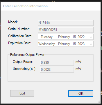
Prior to running the Internal Calibration Accuracy test, you are required to enter the 1 mW reference output power and the calibration uncertainty of the power meter used as the test equipment in the performance test and adjustment mentioned. This calibration information is required rather than the default information to be able to proceed with this test and adjustment.
The following standard checks are performed at the beginning of the Internal Calibration Accuracy test.
|
Device |
Parameter Name and Description |
Limits |
| Power Meter | Output Power (mW) The 1 mW reference output power |
Must be ≥0.99 mW and ≤1.01 mW |
| Uncertainty
(+/-) (mW) The uncertainty of the output power, in absolute value |
Must be ≥0.0015 mW and ≤0.0035 mW |
When running a test that required the calibration data, the test will check if all the required calibration data exists. If it is not, an error message will be prompted to ask you to enter the data.
Table 1 lists the UUT factory predefined frequency points at which the calibration data is required for the external test equipment (ETEs) for each UUT model.
Table 2 lists the equipment that needs to be calibrated at the specific frequency points listed in Table 1.
Please have your ETEs calibrated at those frequency points and enter the calibration data in TME before you run any test.
|
Option 504 |
Option 518 |
Option 526 |
Option 550 |
|
Frequency GHz |
Frequency GHz |
Frequency GHz |
Frequency GHz |
|
0.0001 |
|
|
|
|
0.0003 |
|
|
|
|
0.0005 |
|
|
|
|
0.001 |
|
|
|
|
0.003 |
|
|
|
|
0.005 |
|
|
|
|
0.01 |
0.01 |
0.01 |
|
|
0.03 |
0.03 |
0.03 |
0.03 |
|
0.05 |
0.05 |
0.05 |
0.05 |
|
0.1 |
0.1 |
0.1 |
0.1 |
|
100 MHz step |
100 MHz step |
100 MHz step |
100 MHz step |
|
4.2 |
18 |
26.5 |
50 |
|
Equipment Type |
Performance Test |
||||
|
VSWR |
Calibration Factor |
||||
|
N5532A/B |
N5532A/B |
N5532A/B |
N5532A/B |
||
|
StandardPowerSensor1 |
|
*range2 |
* |
* |
* |
|
StandardPowerSensor2 |
|
*range1 |
|
|
|
|
VerificationPowerSensor1 |
|
*range2 |
* |
* |
* |
|
VerificationPowerSensor2 |
|
*range1 |
|
|
|
|
PowerSplitter1 N F |
|
*range2 |
* |
|
|
|
PowerSplitter2 N F |
|
*range1 |
|
|
|
|
PowerSplitter1 3.5 mm F |
|
|
|
* |
|
|
PowerSplitter1 2.4 mm F |
|
|
|
|
* |
|
Network Analyzer 1-Port |
* All UUT1 |
|
|
|
|
* Refer to Table 1 for the
required frequency points
range 1: 100 kHz – 50 MHz
range 2: 50 MHz – 4.2 GHz
When power sensor is selected as Network Analyzer 1-Port Cal Verification Device 1, the required frequency points are in Table 1. When verification kit is selected as Network Analyzer 1-Port Cal Verification Device 1, the software will use the calibration data come with the verification kit which may or may not match the frequency points in Table 1.
|
|
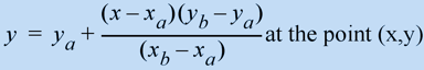
In the situation where you choose to run the VSWR and Calibration Factor test with additional frequency points, the test setup verification in those two tests will still only verify the factory predefined data points. If the calibration data of the additional frequency points for the power splitter or the standard power sensor are not available, linear interpolated calibration data will be generated and used for those points when calculating calibration factor and the associated uncertainty. The linear interpolation data is calculated by the following formula:
where y is the calibration data and x is the frequency associated with the calibration data |
CITIfile is a standardized data format that is used for exchanging data between different computers and instruments. CITIfile stands for Common Instrumentation Transfer and Interchange file format. Below is an example of the CITIfile format calibration data files for the power splitter generated by the Keysight Standard Lab and the steps to generate TME required calibration data.
A power splitter of serial number 12345 has two files: 12345d and 12345u. One contains data and the other contains uncertainty.
12345d — This data file
contains the S11, S21, S31, C22 (Port 2 equivalent source match), C33
(Port 3 equivalent source match), and tracking data.
These data are in real and imaginary format.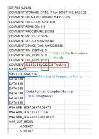
12345u — This uncertainty
file contains the uncertainty of S11, S21, S31, C22, C33, and Tracking.
These data are magnitude uncertainty and phase uncertainty (degree).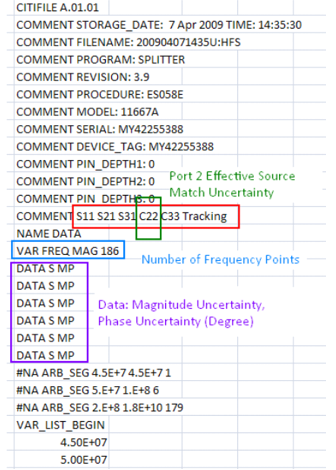
The calibration data TME needs are Port 2 Source Match, Port 2 Source Match Phase (Degree), Port 2 Source Match Uncertainty, and Port 2 Source Match Phase Uncertainty (Degree)
Port 2 Source Match and Port 2 Source Match Phase (Degree)
Import the 12345d to an excel spreadsheet.
Copy
the frequencies to a column.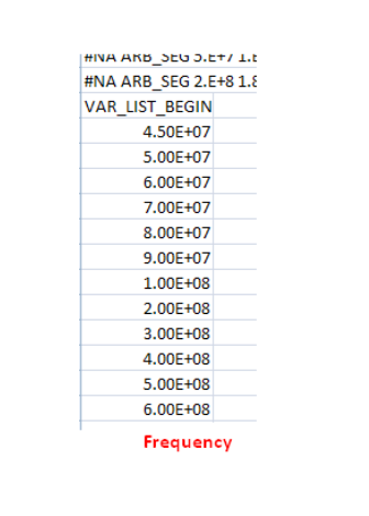
Copy
the 4th data block (C22 data block) after the frequency block to separate
columns.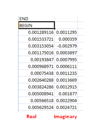
Convert
the (real, imaginary) data to (magnitude, phase[degree]) data. TME requires
the phase to be a value between -180 and +180 degree. When converting
the data, be sure to check the sign of the real and imaginary part to
make sure the generated phase (degree) is in the correct quadrant.
If you are using Microsoft Excel 2007, the following functions
can be used to do the conversion.
’r;COMPLEX’ to create a complex number with the real and imaginary values.
’r;IMABS’ to calculate the magnitude of a complex number.
’r;IMARGUMENT’ to calculate the phase of a complex number in radian.
’r;DEGREE’
to convert the phase in radian to phase in degree.
Port 2 Source Match Uncertainty and Port 2 Source Match Phase Uncertainty (Degree)
Import the 12345u to an excel spreadsheet.
Copy
the 4th data block (C22 uncertainty data block) after the frequency block
to separate columns. The 1st column is the uncertainty of the magnitude
of the port 2 effective source match. The 2nd column is the uncertainty
of the phase (degree) of the port 2 effective source match. No data conversion
is needed for these two columns.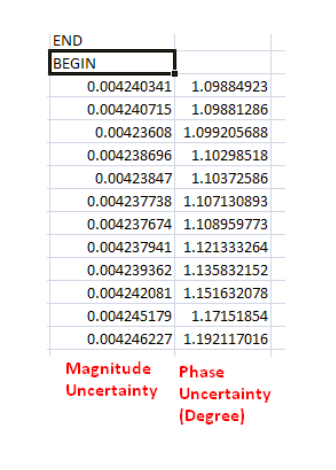
Create a new spreadsheet to put the required data together.
Copy the frequency column (from 1.b) to the 1st column.
Copy the Port 2 source match magnitude (from 1.d) to the 2nd column.
Copy the Port 2 source match magnitude uncertainty (from 2.b) to the 3rd column.
Copy the Port 2 source match phase (degree) (from 1.d) to the 4th column.
Copy the Port 2 source match phase uncertainty (degree) (from 2.b) to the 5th column.
Save this spreadsheet as a CSV (comma delimited) file.
Follow the instructions in TME Calibration Data XML File Generation Utility to generate a TME importable XML file with the csv file and import the XML file into TME.
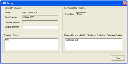
Z2092B-208 is a predefined TME calibration option for the Z2090B-207 Power Sensor test system. The Z2090B-207 Power Sensor test systems with option Z2092B-208 has a Network Analyzer lower frequency limit of 10 MHz. If this option is selected during the order creation of an N5532x Option 504 or U5532C Option 504 Unit Under Test (UUT), a limited calibration will be performed on the UUT.
VSWR will only be measured from 10 MHz to 4.2 GHz. The determination of Cal factor assumes the UUT meets it VSWR specifications for frequencies below 10 MHz. This results in higher Calibration Factor uncertainty for this limited calibration below 10 MHz.
The calibration data of the splitters and the standard and verification power sensors are still required for the full frequency range 100 kHz to 4.2 MHz (see Table 1 for the required calibration data).