


Introduction
The Keysight 89600 VSA is a signal processing toolkit that spans applications in emerging communications standards, aerospace defense, cellular, wireless and the Internet of Things. In some situations, an engineer may want to directly use the VSA software to analyze IQ data from their custom hardware or software. While the VSA offers hardware connectivity options with over 300 Keysight model numbers and file-based record and playback approaches, the direct data connectivity enables a more seamless approach.
Using the new “Direct Data Connectivity” option, users can now apply Keysight’s sophisticated measurement IP, interactive visualization, and automation tools to a richer set of data sources, including
- Data from the inside of your signal processing chain, such as the baseband IQ from your own receiver (rather than a transmitter)
- Data from a preferred HW acquisition source, including 3rd party or custom measurement solutions, which may also be performing a variety of other functions
- Data from software streams, simulated environments, deeper offline recording files, and multi-channel data that was captured manually or sequentially
In this brief application note, we will illustrate how to use the VSA .NET API (UserInput classes) to programmatically push RF time domain IQ data to the VSA from your own application.
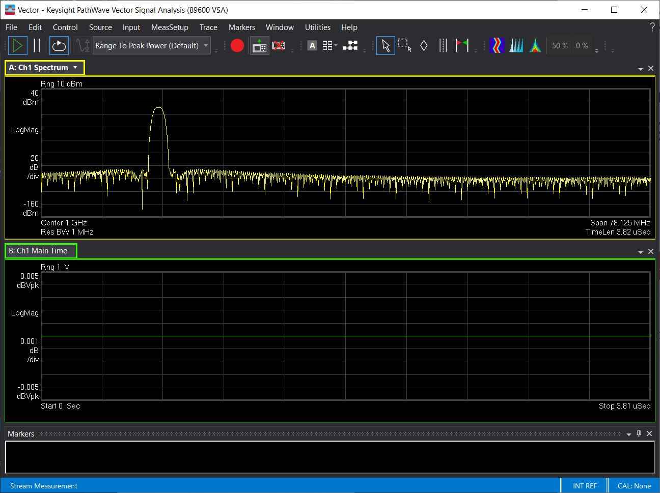
Figure 1. Output results from the example application in VSA
Background
There are three ways to get IQ data into the VSA: hardware acquisition, recording files and Direct Data Connectivity. Hardware acquisition is the most common method, where IQ data is acquired from instruments like analyzers and scopes. The VSA is also capable of retrieving and playing recording files, which could be saved from a prior hardware acquisition or IQ data stored in a database. Direct Data Connectivity allows a user to push live IQ data into the VSA without the use of supported hardware or recording files. This data may come from many sources – hardware that does not have a VSA adapter, simulation results, data stored in a test results database, or a subset of a data stream.
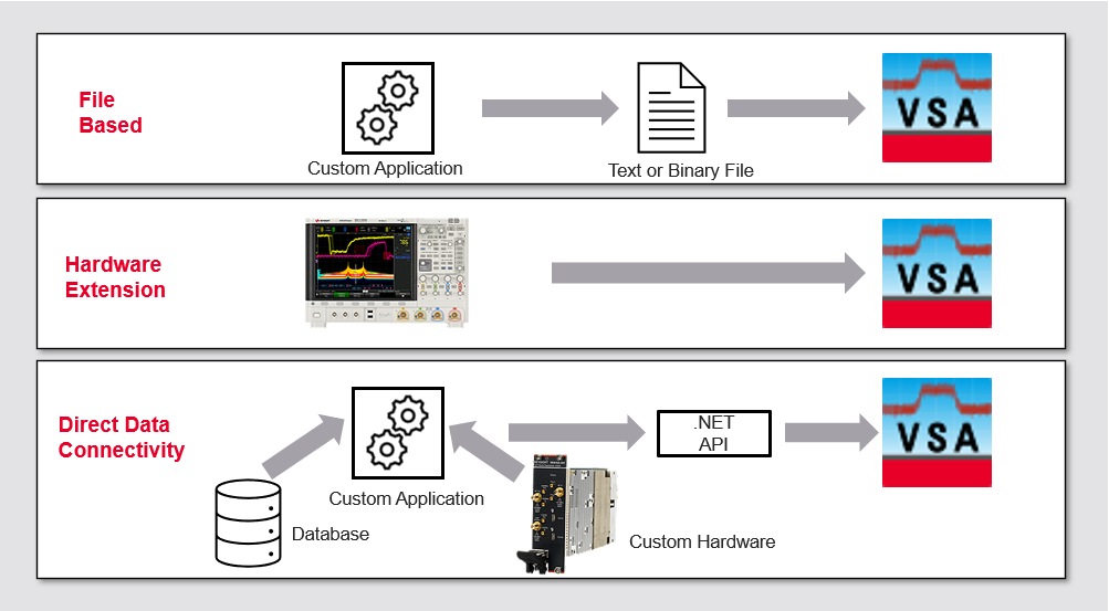
Figure 2. Three types of data input into VSA.
The Role of the Data Provider
For the VSA to correctly handle the IQ data pairs, the IQ data provider application must provide important metadata such as center frequency, bandwidth, sample rate, amplitude scaling, the maximum requestable record size and whether the data is complex or real. In a typical situation where the VSA obtains data from hardware, it queries the hardware driver for such information. On the other hand, when using Direct Data Connectivity, the user application needs to know and set these data parameters.
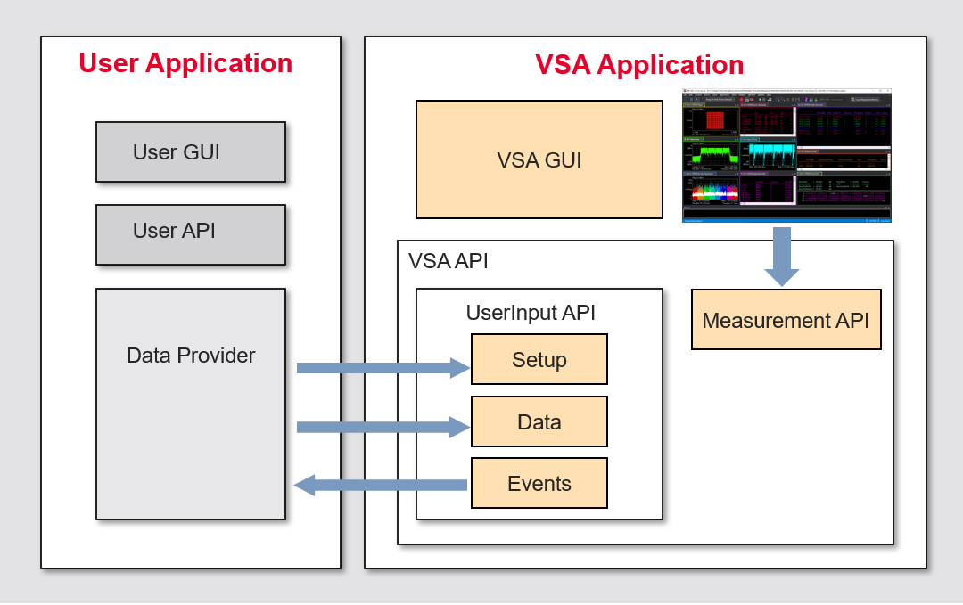
Figure 3. Interactions between the user application and VSA
Direct Data Connectivity UserInput API Classes
Within the Agilent.SA.Vsa.Interfaces library, the UserInput classes are at the heart of the data push to the VSA.
- UserInput – This is the main class that sets the number of channels and provides a reference to the other three classes. There is one UserInput class for every hardware/software configuration.
- UserInputSetup – This is where the metadata parameters are set like center frequency, span, full scale amplitude, etc. It can be set up once for all channels or on a per-channel basis by using its “Channels” property.
- UserInputData – This is the actual data construct that contains the IQ data pairs. It also contains feedback information from the VSA, acknowledging the success (or lack thereof) of the data transfer.
- UserInputChangeRegister – This contains two properties that notify the application when properties have changed in the UserInputData setup.
Setup and Order of Execution
The Direct Data Connectivity example application can be found in the following directory of the VSA user installation:
<VSA Install Directory>\Examples\DotNET\C#\DirectDataConnectivityConsoleDemo
 |
You will need to copy the contents of the Examples directory to your Documents directory or some other location that is writable before compiling and running the example programs since the contents of the VSA installation directory are read-only. The examples depend on API interfaces under the Interfaces directory of your VSA software installation, so you may also need to repair references to these interfaces before the example will run. |
For this code to compile and run, a reference to the Agilent.SA.Vsa.Interfaces.dll assembly is required. Opening this solution with Visual Studio in the installed location will find this assembly. If you need to move the solution to another location to build and run, a new reference to the assembly will need to be added.
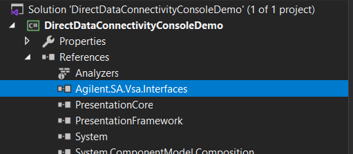
Figure 4: The Agilent.SA.Vsa.Interfaces reference in The Visual Studio solution.
The following items are required to successfully build and run this application:
- Visual Studio 2017 or 2019 with the C# and .NET desktop development environment configured.
- A 2022 Update 1 or newer with the Direct Data Connectivity license or a Trial license.
This example application goes through four main steps to demonstrate the capability.
- Connect to an existing VSA instance or start a new one.
- Create and select a direct data transfer configuration.
- Set up the UserInput classes to describe the data to be pushed to VSA.
- Send the data to VSA.
The Example Code Explained
The following subsections will discuss the four main steps of the example application in more detail.
1. Connect to VSA
// Get a handle to the VSA Application object
// The Create() method with no args will connect to a running VSA
_app = ApplicationFactory.Create();
if ((app == null))
{
// There is no instance of VSA running. Create one.
_app = ApplicationFactory.Create(true, null, null, -1);
_app.IsVisible = true;
}
if (_app == null)
{
Console.WriteLine(string.Empty);
Console.WriteLine("VSA running instance could not be created. Check your VSA installation. Press any key to exit.");
Console.ReadKey();
return;
}
This example shows how to connect to and control an existing instance of VSA running on the user system. If one is not found, it will start a new instance and wait for it to start up and run. All macro examples will begin with this code and is leveraged from VSA’s macro recording capability when you choose to edit a saved macro with Visual Studio.
2. Create and Select Direct Data Configuration
// Create the hardware configuration, select it manually
// Get or create a hardware configuration
var hardwareConfigurationName = "DirectDataSource";
var _hardwareConfiguration = app.Hardware.Configurations[hardwareConfigurationName];
if (_hardwareConfiguration == null)
{
_hardwareConfiguration = app.Hardware.Configurations.Create(hardwareConfigurationName);
}
// Setup hardware configuration for use by UserInput
string instrumentAddress = "USR::Stream";
_hardwareConfiguration.Groups.Clear();
_hardwareConfiguration.Groups.Create(instrumentAddress);
_hardwareConfiguration.Groups.ApplyChanges();
A hardware configuration is required to use the UserInput classes. There are different logical instrument types for the various hardware that VSA supports. For example, the Keysight/Agilent Infiniium Series Oscilloscope instrument will use a SIM::Infiniium address to represent a simulated oscilloscope. For this example, the logical instrument is a Keysight VSA Stream, and the instrument address can be seen in the code as USR::Stream. The hardware configuration is named “DirectDataSource”. The application checks whether a hardware configuration by the same name exists. Such a situation could exist where the configuration is left over from a previous run of the example app when it exits abnormally. When the app exits normally, the VSA will clean up and remove this configuration at the end of the run. After creation, the user will be prompted in the console window to select this new configuration via the VSA GUI as the active one. Next, the VSA status at the bottom left of the GUI should state “Filling Time Record”, indicating that the VSA is waiting for new data.
3. Set Up the UserInput Properties
// Get a reference to the current user input object
_userInput = _app.Measurements.SelectedItem.SelectedAnalyzer.Groups[0].UserInput;
var configName = _app.Measurements.SelectedItem.SelectedAnalyzer.Groups[0].Name;
// Check if UserInput is available and licensed.
if (_userInput.Enabled)
{
#region Setup UserInput Classes
_userInput.Setup.IsImmediateChangesEnabled = false;
// Set values that don't match what VSA already defaults.
_channelCount = 1;
_userInput.ChannelCount = _channelCount;
_userInput.UserInputChange.Mask = UserInputChangeBits.IsRequiredSamplesPositive;
_userInput.Setup.SetFrequencyParameters(true, 1e9, 1e8, 1e8 / 1.28);
_userInput.Setup.CaptureSizeMaximum = 1e6;
_userInput.Setup.IsContinuousCapable = false;
_userInput.Setup.ApplyChanges();
The first line of code provides a reference to the UserInput class associated with our newly created DirectDataSource hardware configuration. The name of the configuration may be double-checked with the configName field, just to ensure we have the correct configuration during debugging. Once the reference is obtained from the SelectedItem, it can be used to configure all the necessary UserInput classes. The characteristics of the signal are now set in the UserInput.Setup class. The number of channels is set to 1 via _channelCount. To increase the number of channels, the user will need to change the _channelCount value and then use the VSA GUI Input menu to select the same number of channels. The SetFrequencyParameters() method call sets whether the data is complex (true), the center frequency (1 GHz), the sample rate (100 MHz) and the span (100 MHz / 1.28). The UserInputChange.Mask property will be covered later in the Polling vs. Event Driven section below. It is not used in the operation of the console application since it does not set up any notification events. Finally, with all the metadata and UserInput properties set, the ApplyChanges() method is called to update VSA.
4. Send the Data
// Query for the number of samples the measurement requires
var samples = _userInput.Data.RequiredSamples;
var changed = _userInput.UserInputChange.Value;
_sendDataBlockSize = (int) samples;
...
// Allocate the buffer based on channel count.
UpdateSendDataBufferAllocation();
// Send data to VSA
SendDataOnce();
Once the UserInput parameters have been applied, we can get the number of samples that the VSA is requesting to properly display the data. For reference only, the UserInputChange value is read so that we can verify that the status indicates that VSA is waiting for points (the Value property has the flag IsRequiredSamplesPositive set). This is the status bit that we enabled earlier on with the Mask property. The app then updates the send buffer based on the number of IQ samples and number of channels needed. The last step is simply to send the data to VSA. The method userInput.Data.SendData(sendBuffer) is the line of code in the SendDataOnce() method that does the push to the VSA buffer. The simulated data from the console application should now be displayed in the time and frequency traces that were configured in VSA, as shown in Figure 1 of this document.
The user is now prompted to enter ‘y’ to send another block of data or any other key to cleanup and exit. On exit, VSA is set back to the original hardware configuration and the DirectDataSource configuration is deleted. The RequiredSample property is retrieved and verified to be greater than zero prior to sending subsequent blocks. Since the measurement setup has not been changed between sending blocks of data, the same amount of data is sent each time.
Polling vs. Event Driven
Since this example is a console application that only pushes data to VSA when the user presses a key, the data rate into VSA is slow and on-demand by the user. For a situation where the application can provide a stream of IQ data and continuous updating of data is required, using notification events may be the better approach. As shown earlier, notification events can be attached to a property on the UserInputData or the UserInputChangeRegister class. The DirectDataConnectivityWpfDemo solution demonstrates how to implement the event-based model.
Conclusion
Utilizing the Direct Data Connectivity for VSA can be a convenient and effective method to visualize and analyze data that is obtained from sources other than Keysight hardware. The data may come from many places, from simulations to archived production test databases. With the VSA, this data may be visualized and analyzed with all the latest test models across cellular, wireless LAN and emerging R&D. The different polling and event driven models give the user flexibility to choose the right method based on infrequent “eavesdropping” to continuous data streaming, enabling VSA to be an important signal analysis tool within a larger solution.