Reference Impedance (Input Analog Tab)
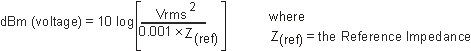
The parameter specifies the reference impedance "Z(ref)" value that the VSA uses to calculate the power in dBm deciBels referenced to a milliWatt: dB relative to 1 milliwatt dissipated in the nominal input impedance of the analyzer for the selected Logical Channel. The VSA uses the following equation to compute dBm. dBm is the power in decibels referenced to a milliWatt.
The Reference Impedance can be specified to match the by selecting Same as Input or set separately by clearing the checkbox and entering an impedance in the text box.
This parameter can be selected for channels or individually for each available channel. The available channels are displayed in located at the top of the dialog box. If the selections for individual channels are different, the arrow button ( ) after the text box will be orange. Click the arrow button to view the selection for each available channel.
Measurement Concepts
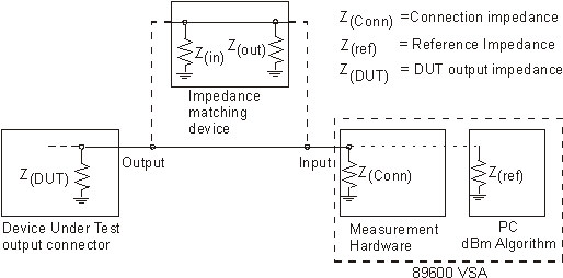
When the DUT Device under Test: An acronym used to describe some type of electrical apparatus connected to test instrumentation. The apparatus can range from a single component to a complex subsystem such as a mobile phone, base station or MSC. and measurement hardware input impedance are the same, the checkbox is selected. No changes are required to the or parameters.
When there is an impedance mismatch between the DUT and the input of the measurement hardware, the checkbox is cleared. The parameter is used in conjunction with the parameter to calculate dBm. The VSA algorithm uses the measured voltage and the Reference Impedance value to calculate the power in dBm. Also, any impedance matching device insertion loss can be compensated for using the parameter ().
The following steps show how to set up a measurement when there is a DUT and measurement hardware input impedance mismatch.
- Set the Input Impedanceparameter to match the impedance of the impedance-matching device that is connected to the input of the measurement hardware.
- Clear the Same as Input checkbox.
- Specify the to match the DUT output characteristic impedance.
- If an impedance
matching device, attenuator, or measurement probe that has insertion loss is used,
compenaste with the parameter:
- Click
- Click the check box.
- Specify the insertion loss compensation value in the parameter.
Reference Impedance Measurement Examples
|
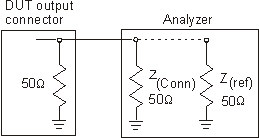
If the device under test has an output impedance that matches the measurement hardware input impedance, set to match the DUT impedance and select . Because the two impedances match, no external amplitude calibration is required. |
|
|
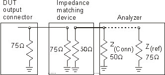
If the output impedance of the device under test and the input impedance of the measurement do not match, use an impedance-matching device. The impedance-matching device must have an input impedance equal to the output impedance of the device under test and an output impedance equal to the measurement hardware's input impedance. In this case, set the following parameters:
|
|
The VSA corrects the amplitude based on the correct and settings but the Input Range is set relative to the VSA input and not the impedance converter input.
See Also