Composite Symbol Table (TEDS)
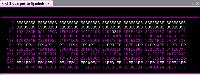
The composite displays all the symbols for the selected slot format (Normal Downlink, Normal Uplink, Random Access, and Control Uplink). The image below is Normal Uplink, 50kHz channel bandwidth, 16QAM modulation signal. The symbols start with sync () symbols, followed by data symbols, interspersed with pilot () and header symbols. The sync, pilot and header symbols are all shown in white, while the data is in a color. The header symbols show an instead of data when Include -Header Symbols is cleared. (For the Random Access slot format, there are no header symbols.) See Slots and Symbols to learn more about the slot formats.
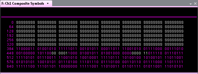
The symbols can also be displayed in the binary format. To select Hex or Binary for your symbol table format, see . The image below is for the same signal (Normal Uplink, 50kHz channel bandwidth, 16QAM modulation) but in binary format.
The composite Symbol Table shows the composite (combined) symbols for all subcarriers. The quantity of subcarriers varies with your channel bandwidth and the number of symbols per subcarrier varies with your slot format. See TEDS Subcarriers for more information. Each hex data symbol represents 4 bits regardless of the downlink or uplink slot format. The header symbols represent 2 bits. See Symbol Constellations for more information.
There is a different number of bits per symbol for each modulation type. For 4QAM (QPSK Quadrature phase shift keying), which is 2 bits per symbol, the display is in binary, even if the symbol table format is set for hex, and the symbols appear in binary pairs. Thus the symbol display starts with sync pairs, followed by symbol pairs for the data symbols, interspersed with header and pilot symbols. Note that for the Random Access slot format, there are no header symbols.
For 16QAM, which is 4 bits per symbol, the symbol table (in hex) maps neatly to the sync symbols, followed by 4-bit data symbols, interspersed with 2-bit header symbols and pilot symbols.
For 64QAM, which is 6 bits per symbol, the symbol table display doubles (in hex) because the symbols appear in pairs with 2 bits for the most significant symbol and 4 bits for the least significant symbol. Thus the symbol display starts with sync pairs, followed by symbol pairs for the data symbols, interspersed with header and pilot symbols.
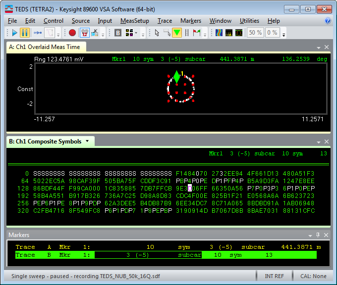
Correlating a Composite Symbol Table and Constellation Diagram
To correlate a symbol in a subcarrier IQ Time constellation diagram with a
symbol in the composite symbol table, display
the constellation diagram in one trace window, display
the Composite Symbol Table in another trace window, then select Marker > (Add marker  ) followed by . Pause
the recording and select a symbol in the symbol table to
highlight the corresponding I-Q point in the constellation diagram. Use your mouse-wheel
or keyboard arrow keys to move to symbols in the table and note the corresponding
symbol position in the constellation diagram and the Marker position information
at the bottom of the screen (subcar, sym number, and so forth).
) followed by . Pause
the recording and select a symbol in the symbol table to
highlight the corresponding I-Q point in the constellation diagram. Use your mouse-wheel
or keyboard arrow keys to move to symbols in the table and note the corresponding
symbol position in the constellation diagram and the Marker position information
at the bottom of the screen (subcar, sym number, and so forth).
See Also