CDP Composite (W-CDMA(3GPP)/HSPA)
trace shows the power in each channel for the composite signal. Code Domain Power (CDP) is an analysis of the distribution of signal power across the set of normalized to the total signal power. When Normalize IQ Traces is on, the power is expressed in dBc deciBels referenced to the carrier: A technique for expressing a power measurement in logarithmic form using the carrier power as a reference., and is relative to the total power in the signal. When is off, the power is expressed in dBm deciBels referenced to a milliWatt: dB relative to 1 milliwatt dissipated in the nominal input impedance of the analyzer. If the Measurement Interval is greater than one, all slots within the are averaged together to produce the results.
trace data results are computed only from the first measured Slot after the Measurement Offset.
View CDP trace data as absolute power by clearing the check box ().
Display Format
The data is shown in a multi-color format that assigns a unique color to each code layer and related active . This makes it easy to visually identify and distinguish the active for a given code layer (Spread Code Length). The colors are also user definable (see Display Preferences > Color tab).
The y-axis shows the power level and the x-axis shows the . The x-axis annotation and marker location are based on the lowest symbol rate (ksym/sec), or equivalently, the highest Spread Code Length. Use the code order format parameter to rearrange the placement the displayed (see Code Order).
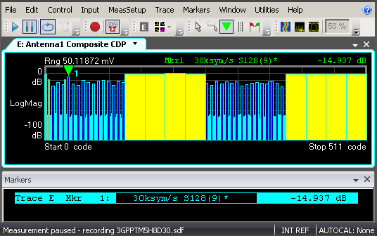
This example Antenna 1 Composite CDP display Trace A Marker shows the following:
|
Symbol Rate: |
30 Ksym/s |
|
Spread Code Length: |
128 |
|
Code Channel: |
9 |
|
Power Level: |
-14.937 dB |
|
Asterisk *: |
The asterisk (*) indicates that the marker is positioned on an active channel. |
Use the CDP Layer trace data display to view only one code layer () at a time.
See Also
About Measurement Interval and Offset