About HSPA+ MIMO Analysis
This topic describes the capabilities of the HSPA+MIMO Multiple Input, Multiple Output: A physical layer (PHY) configuration in which both transmitter and receiver use multiple antennas. feature of Option B7U: W-CDMA Code Division Multiple Access: One of several digital wireless transmission methods in which signals are encoded using a specific pseudo-random sequence, or code, to define a communication channel. A receiver, knowing the code, can use it to decode the received signal in the presence of other signals in the channel. This is one of several "spread spectrum" techniques, which allows multiple users to share the same radio frequency spectrum by assigning each active user an unique code. CDMA offers improved spectral efficiency over analog transmission in that it allows for greater frequency reuse. Other characteristics of CDMA systems reduce dropped calls, increase battery life and offer more secure transmission. See also IS-95. (3GPP)/HSPA.
HSPA+ MIMO feature adds signal measurement analysis for 2x2 DL Down Link (forward link: from base station to cell phone) MIMO systems for HS-PDSCH High Speed Physical Downlink Shared Channel signals using flat-fading. Connect Antenna 1 and Antenna 2 of the Downlink transmitter to the two-input channel analysis hardware, and the 89601A will provide MIMO analysis capability for the HSPA+MIMO signal. Also connect Antenna 1 or Antenna 2 to single-input channel analysis hardware and the 89601A will provide single channel analysis capability for each channel independently.
The HSPA+ MIMO feature supports MIMO analysis for the following HSPA+MIMO signal format:
- 2x2 DL MIMO for HS-PDSCH Physical Downlink Shared Channel as defined in 3GPP TS25.214 v.8.5.0(2009-03), chapter 9.
- Flat fading (Frequency-selective fading not supported at this time).
Topic Contents:
Making a HSPA+MIMO 2x2 Measurement
This procedure applies to MIMO analysis for a 2x2 DL MIMO system for HS-PDSCH signals using flat-fading.
Measurement Setup
- Connect the Tx Antenna input signals to the VSA measurement hardware input(s), configure the VSA hardware settings and specify the VSA number of (). The VSA can perform two-input channel or single-input channel MIMO analysis.
- Two-input channel analysis hardware: Connect Antenna 1 and Antenna 2 of the Downlink transmitter to the two-channel analysis hardware and the 89601A will provide MIMO analysis capability for the HSPA+MIMO signal.
- Single-input channel analysis hardware: Connect Antenna 1 or Antenna 2 to single channel analysis hardware and the 89601A will provide single channel analysis capability for each channel independently.
Configure the VSA demodulator (W-CDMA(3GPP)/HSPA Demod Properties dialog):
- Select Downlink Direction (Format tab).
- Select Enable HSPA analysis (Format tab).
- Specify a 2 Tx antenna measurement, see Number of Tx Antennas (Format tab).
- Specify a Spread Code Length 16 (240 ksym/s) (Channel/Layer tab)
- Specify the MIMO parameter settings. The MIMO parameters are used to further define the HSPA+ MIMO signal characteristics.
When the number of transmit antennas is 2, the VSA performs MIMO analysis and the MIMO Advanced parameters are enabled.
Using Freq Offset Model parameter
The parameter selects which impairment model to use for WCDMA HSPA+MIMO measurements of Frequency Offset. When "Rx" is selected, the receiver impairment model is assumed. The transmitter locks between antenna ports and the measurement estimates receiver frequency offset. When "Tx" is selected, the transmitter impairment model is assumed.The receiver is assumed to have locked frequency clocks between input ports and the measurement estimates transmitter frequency offset. Note that the Freq Offset Model will have an impact on how to interpret the MIMO Info summary table results for "(CPICH Common Pilot Channel) Freq Offset".
HSPA+MIMO Analysis Trace Data Overview
This topic provides an overview of the HSPA+MIMO Trace Data and Parameters that support the HSPA+MIMO analysis. There have been many new trace data results added and updates to the existing trace data results for HSPA+ MIMO analysis, see Available HSPA+MIMO Trace Data and HSPA+MIMO Trace Data Name Revisions respectively.
The MIMO system implementation produces additional signal analysis test points to the W-CDMA signal flow. The VSA provides trace data results for these additional MIMO analysis test points. To understand where within the MIMO signal flow the VSA trace data results apply, see the HSPA+MIMO Trace Mapping Diagram. The HSPA+MIMO Mapping Diagram shows the HSPA+MIMO system test point and related Trace Data results within the MIMO system signal flow.
Selecting an appropriate VSA WCDMA HSPA+MIMO analysis configuration depends on the following factors:
- The number of available VSA input channels,
- The ability to independently enable or disable HS-PDSCH TrBlock transmission,
- The purpose of the measurement (CDP verification, channel coding verification, EVM Error vector magnitude (EVM): A quality metric in digital communication systems. See the EVM metric in the Error Summary Table topic in each demodulator for more information on how EVM is calculated for that modulation format. testing, etc.)
The following table lists the supported MIMO configurations for WCDMA HSPA+MIMO analysis and the available trace data results for a given MIMO signal configuration.
|
MIMO Configuration |
VSA Inputs |
HS-PDSCH (TrBlock1) |
HS-PDSCH (TrBlock2 |
CDP Results |
CDE Results |
Composite Results |
Despread Channel Results |
MIMO Results |
|---|---|---|---|---|---|---|---|---|
| SISO 1-1 | (1)TxAnt1 | Y | - | Y | Y | Y | Y | - |
| SISO 1-2 | (1)TxAnt1 | - | Y | Y | Y | Y | Y | - |
| SISO 2-2 | (1)TxAnt2 | Y | - | Y | Y | Y | Y | - |
| SISO 2-1 | (1)TxAnt2 | - | Y | Y | Y | Y | Y | - |
| MISO 1 | (1)TxAnt1 | Y | Y | Y | - | - | - | - |
| MISO 2 | (1)TxAnt2 | Y | Y | Y | - | - | - | - |
|
MIMO 2X2 |
(2)TxAnt1, TxAnt2 |
Y | Y |
Y (2sets) |
Y (2sets) |
Y (2sets) |
Y (2sets) |
Y |
Available HSPA+MIMO Trace Data
- Antenna 2 Comp Trace Data
- Antenna 2 CDP Trace Data
- Channel 2 Trace Data
- Despread (x) Trace Data
- MIMO Info Summary Table
- All Available W-CDMA(3GPP)/HSPA Trace Data
HSPA+ MIMO Trace Data Mapping Diagram
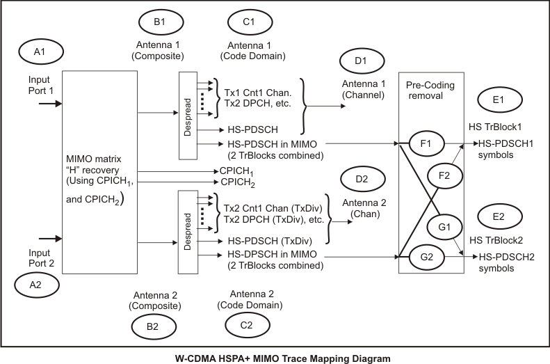
The HSPA+MIMO Trace Data Mapping Diagram shows the various HSPA+MIMO Trace Data measurement categories and the associated measurement Test Plane Location within the HSPA+MIMO analysis signal flow. The HSPA+MIMO Mapping Diagram Reference identifiers (A1, B2, etc.) are used in the HSPA+MIMO Test Plane Location Mapping Table (and other Trace Data topics) to show the VSA measurement test point.
HSPA+MIMO Test Plane Location Mapping Table
The HSPA+MIMO Test Plane Location Mapping Table provides the correlation between the HSPA+MIMO measurement Test Plane Location, the Trace Data Category (and Description), and the DataName for the .NET API 1) Access Preamble Indicator, or 2) Application Programming Interface Trace object. This table is used to determine what Trace Data category of measurements are available at a particular Test Plane Location within the HSPA+MIMO signal flow. The Test Plane Location identifier is used in the HSPA+MIMO Trace Mapping Diagram to show the VSA measurement test point.
- Test Plane Location Identifier: The measurement Test Plane Location Identifier used in the HSPA+MIMO Trace Mapping Diagram to show the VSA measurement test point within the HSPA+MIMO signal flow.
- Trace Data Category: The Trace Data Category of Trace Data results (Despread 1 example: )
- Trace Title Prefix: The Trace Data Category name Prefix that is appended to the Trace Data Title shown in the trace display window.
- Trace Description: Description of the Trace Data result.
- .NET API DataName: The argument used in the .NET API Trace object DataName property.
|
Test Plane Location Identifier |
Trace Data Category | Trace Title Prefix |
Trace Data Category Description |
.NET API DataName |
|---|---|---|---|---|
| A1 | Channel 1 | Ch1 | Pre-demod measurements from input channel 1. | [TRACENAME]1 |
| A2 | Channel 2 | Ch2 | Pre-demod measurements from input channel 2. | [TRACENAME]2 |
| B1 | Antenna 1 Comp | Antenna1 Composite | Composite measurements measured from input channel 1. | Comp [TRACENAME]1 |
| B2 | Antenna 2 Comp | Antenna2 Composite | Composite measurements measured from input channel 2. | Comp [TRACENAME]2 |
| C1 | Antenna 1 CDP | Antenna1 | Code Domain Power measurements measured from input channel 1. | CDP [TRACENAME]1 |
| C2 | Antenna 2 CDP | Antenna2 | Code Domain Power measurements measured from input channel 2. | CDP [TRACENAME]2 |
| D1 | Despread 1 | Antenna1 [RATE] | Despread channel measurements measured from input channel 1. | Chan [TRACENAME]1 |
| D2 | Despread 2 | Antenna2 [RATE] | Despread channel measurements measured from input channel 2. | Chan [TRACENAME]2 |
| E1 | Despread 1 | HSTrBlock1 [RATE] | Despread channel measurements of a HS TrBlock1 signal using signals combined from input channels 1 and 2 (only available for S16 code channels). | Chan [TRACENAME]1 |
| E2 | Despread 2 | HSTrBlock2 [RATE] | Despread channel measurements of a HS TrBlock2 signal using signals combined from input channels 1 and 2 (only available for S16 code channels). | Chan [TRACENAME]2 |
| F1 | Despread 1 | Ant1 HSTrBlock1 [RATE] | Despread channel measurements of a HS TrBlock1 signal using signal from input channel 1 (only available for S16 code channels). | Chan [TRACENAME]1 |
| F2 | Despread 2 | Ant2 HSTrBlock1 [RATE] | Despread channel measurements of a HS TrBlock1 signal using signal from input channel 2 (only available for S16 code channels). | Chan [TRACENAME]2 |
| G1 | Despread 1 | Ant1 HSTrBlock2 [RATE] | Despread channel measurements of a HS TrBlock2 signal using signal from input channel 1 (only available for S16 code channels). | Chan [TRACENAME]1 |
| G2 | Despread 2 | Ant2 HSTrBlock2 [RATE] | Despread channel measurements of a HS TrBlock2 signal using signal from input channel 2 (only available for S16 code channels). | Chan [TRACENAME]2 |
HSPA+MIMO Trace Data Name Revisions
The W-CDMA(3GPP)/HSPA trace names chaned with release 11.20 of the 89601A VSA. The following a following information and table describe these changes.
The nomenclature for W-CDMA(3GPP)/HSPA trace names changed from "Channel 1" and "Channel 2" to "Antenna 1" and "Antenna 2". The trace names were changed to reduce confusion when referring to despread code channels versus input hardware channels. The Trace object DataNames property categories for Composite and CDP traces change from a "Channel 1" prefix to an "Antenna 1" prefix. The trace title strings changed from a "Ch1" prefix to an "Ant1" prefix. Also, because the despread channel results now can refer to multiple test planes within the block diagram, the trace titles and categories for despread channel traces are changed. Despread channel traces will now be in a category named "Despread 1" instead of "Channel 1 Chan". The trace titles will vary based on the specific test plane selected by the user, as described in the table above, and in the description of the Despread traces selection .
This change maintains backwards-compatibility through the COM API. The affected traces are listed in the table below. Note instantaneous versions of an averaged trace (indicated by "Inst" string in the COM DataName), will have a trace title matching the averaged version of the trace unless averaging is enabled. If averaging is enabled, the "Inst" string will appear in the trace title, as indicated in the table below. The [RATE] and [RATECODE] tokens in trace titles depend on the specific code channel which is selected for despread code channel analysis, as well as the layer selected for code layer analysis.
| COM DataName | Category | Trace Title | Previous Category | Previous Title |
|---|---|---|---|---|
| CDP CDE Layer1 | Antenna 1 CDP | Ant1 [RATE] CDE | Channel 1 CDP | Ch1 [RATE] CDE |
| CDP CDP Composite1 | Antenna 1 CDP | Ant1 Composite CDP | Channel 1 CDP | Antenna 1 Composite CDP |
| CDP CDP Layer1 | Antenna 1 CDP | Ant1 [RATE] CDP | Channel 1 CDP | Ch1 [RATE] CDP |
| CDP Code Domain Offsets1 | Antenna 1 CDP | Ant1 Composite Code Domain Offsets | Channel 1 CDP | Antenna 1 Composite Code Domain Offsets |
| CDP Inst CDE Composite1 | Antenna 1 CDP | Ant1 Inst Composite CDE | Channel 1 CDP | Ch1 Inst Composite CDE |
| CDP Inst CDE Layer1 | Antenna 1 CDP | Ant1 Inst [RATE] CDE | Channel 1 CDP | Ch1 Inst [RATE] CDE |
| CDP Inst CDP Composite1 | Antenna 1 CDP | Ant1 Inst Composite CDP | Channel 1 CDP | Ch1 Inst Composite CDP |
| CDP Inst CDP Layer1 | Antenna 1 CDP | Ant1 Inst [RATE] CDP | Channel 1 CDP | Ch1 Inst [RATE] CDP |
| CDP Slot Summary1 | Antenna 1 CDP | Ant1 Composite Slot Summary | Channel 1 CDP | Antenna 1 Composite Slot Summary |
| Chan Error Vector Time1 | Despread 1 | Ant1 [RATE CODE] Err Vect Time | Channel 1 Chan | Ch1 [RATE CODE] Err Vect Time |
| Chan IQ Mag Error1 | Despread 1 | Ant1 [RATE CODE] Mag Error | Channel 1 Chan | Ch1 [RATE CODE] Mag Error |
| Chan IQ Meas Time1 | Despread 1 | Ant1 [RATE CODE] Meas Time | Channel 1 Chan | Ch1 [RATE CODE] Meas Time |
| Chan IQ Phase Error1 | Despread 1 | Ant1 [RATE CODE] Phs Error | Channel 1 Chan | Ch1 [RATE CODE] Phs Error |
| Chan IQ Ref Time1 | Despread 1 | Ant1 [RATE CODE] Ref Time | Channel 1 Chan | Ch1 [RATE CODE] Ref Time |
| Chan Syms/Errs1 | Despread 1 | Ant1 [RATE CODE] Syms/Errs | Channel 1 Chan | Ch1 [RATE CODE] Syms/Errs |
| Comp Error Summary1 | Antenna 1 Comp | Ant1 Composite Error Summary | Channel 1 Comp | Antenna 1 Composite Error Summary |
| Comp Error Vector Spec1 | Antenna 1 Comp | Ant1 Composite Err Vect Spectrum | Channel 1 Comp | Antenna 1 Composite Err Vect Spectrum |
| Comp Error Vector Time1 | Antenna 1 Comp | Ant1 Composite Err Vect Time | Channel 1 Comp | Antenna 1 Composite Err Vect Time |
| Comp IQ Mag Error1 | Antenna 1 Comp | Ant1 Composite Mag Error | Channel 1 Comp | Antenna 1 Composite Mag Error |
| Comp IQ Meas Spec1 | Antenna 1 Comp | Ant1 Composite Meas Spectrum | Channel 1 Comp | Antenna 1 Composite Meas Spectrum |
| Comp IQ Meas Time1 | Antenna 1 Comp | Ant1 Composite Meas Time | Channel 1 Comp | Antenna 1 Composite Meas Time |
| Comp IQ Phase Error1 | Antenna 1 Comp | Ant1 Composite Phs Error | Channel 1 Comp | Antenna 1 Composite Phs Error |
| Comp IQ Ref Spec1 | Antenna 1 Comp | Ant1 Composite Ref Spectrum | Channel 1 Comp | Antenna 1 Composite Ref Spectrum |
| Comp IQ Ref Time1 | Antenna 1 Comp | Ant1 Composite Ref Time | Channel 1 Comp | Antenna 1 Composite Ref Time |
| Comp Inst Error Vector Spec1 | Antenna 1 Comp | Ant1 Inst Composite Err Vect Spectrum | Channel 1 Comp | Ch1 Inst Composite Err Vect Spectrum |
| Comp Inst IQ Meas Spec1 | Antenna 1 Comp | Ant1 Inst Composite Meas Spectrum | Channel 1 Comp | Ch1 Inst Composite Meas Spectrum |
| Comp Inst IQ Ref Spec1 | Antenna 1 Comp | Ant1 Inst Composite Ref Spectrum | Channel 1 Comp | Ch1 Inst Composite Ref Spectrum |
Antenna 2 Comp Trace Data (Downlink only)
Menu Path:
Composite traces for "Antenna 2" for the HSPA+MIMO measurement. These traces are identical to the "Antenna 1" composite traces, except they are computed from the second antenna. These traces are available for Downlink measurements. The following traces are available in the "Antenna 2 Comp" traces category.
| COM DataName | Category | Trace Title |
|---|---|---|
| Comp Error Summary2 | Antenna 2 Comp | Ant2 Composite Error Summary |
| Comp Error Vector Spec2 | Antenna 2 Comp | Ant2 Composite Err Vect Spectrum |
| Comp Error Vector Time2 | Antenna 2 Comp | Ant2 Composite Err Vect Time |
| Comp IQ Mag Error2 | Antenna 2 Comp | Ant2 Composite Mag Error |
| Comp IQ Meas Spec2 | Antenna 2 Comp | Ant2 Composite Meas Spectrum |
| Comp IQ Meas Time2 | Antenna 2 Comp | Ant2 Composite Meas Time |
| Comp IQ Phase Error2 | Antenna 2 Comp | Ant2 Composite Phs Error |
| Comp IQ Ref Spec2 | Antenna 2 Comp | Ant2 Composite Ref Spectrum |
| Comp IQ Ref Time2 | Antenna 2 Comp | Ant2 Composite Ref Time |
| Comp Inst Error Vector Spec2 | Antenna 2 Comp | Ant2 Inst Composite Err Vect Spectrum |
| Comp Inst IQ Ref Spec2 | Antenna 2 Comp | Ant2 Inst Composite Ref Spectrum |
Antenna 2 CDP Trace Data (Downlink only)
Menu Path:
Code Domain (CDP) Trace Data for "Antenna 2" for HSPA+MIMO measurements. Code Domain (CDP) Trace Data are identical to the "Antenna 1 CDP" composite traces, except they are computed from the second antenna instead of the first antenna. These traces are available for Downlink measurements. The following traces are available in the "Antenna 2 CDP" traces category.
| COM DataName | Category | Trace Title |
|---|---|---|
| CDP CDE Composite2 | Antenna 2 CDP | Ant2 Composite CDE |
| CDP CDE Layer2 | Antenna 2 CDP | Ant2 [RATE] CDE |
| CDP CDP Composite2 | Antenna 2 CDP | Ant2 Composite CDP |
| CDP CDP Layer2 | Antenna 2 CDP | Ant2 [RATE] CDP |
| CDP Code Domain Offsets2 | Antenna 2 CDP | Ant2 Composite Code Domain Offsets |
| CDP Inst CDE Composite2 | Antenna 2 CDP | Ant2 Inst Composite CDE |
| CDP Inst CDE Layer2 | Antenna 2 CDP | Ant2 Inst [RATE] CDE |
| CDP Inst CDP Composite2 | Antenna 2 CDP | Ant2 Inst Composite CDP |
| CDP Inst CDP Layer2 | Antenna 2 CDP | Ant2 Inst [RATE] CDP |
| CDP Slot Summary2 | Antenna 2 CDP | Ant2 Composite Slot Summary |
Channel 2 Trace Data
Menu Path:
Trace Data for the VSA input "Channel 2". These Trace Data results are identical to the "Channel 1" trace data results, except computed from the VSA second input channel. The following trace data is available in the "Channel 2" tracedata category.
| COM DataName | Category | Trace Title |
|---|---|---|
| CCDF2 | Channel 2 | Ch2 CCDF Complementary Cumulative Distribution Function |
| CDF2 | Channel 2 | Ch2 CDF Cumulative Distribution Function: The cumulative probability that a parameter will be less than a given value X. |
| Correction2 | Channel 2 | Ch2 Correction Spectrum |
| Inst Spectrum2 | Channel 2 | Ch2 Inst Spectrum |
| PDF2 | Channel 2 | Ch2 PDF 1) Probability Density Function Trace Data, or 2) Portable Document Format (PDF) created by Adobe Systems is an open standard for document exchange. |
| Raw Main Time2 | Channel 2 | Ch2 Raw Main Time |
| Spectrum2 | Channel 2 | Ch2 Spectrum |
| Time2 | Channel 2 | Ch2 Time |
Despread (x) Trace Data
To select a particular Despread (x) Category Trace Data MIMO result, you need to first determine the appropriate HSPA+MIMO measurement Test Plane for the desired Despread (x) Trace Data result. Then use the "Despread Traces" property to configure the VSA. You use the HSPA+MIMO Trace Mapping Diagram and Test Plane Location Mapping Table to determine the correct Despread measuremen MIMO Test Plane. You use the Despread Channel "Despread Traces" parameter to configure the VSA.
Despread Traces Property (Channel/Layer tab)
Menu Path for parameter: tab
Menu Path for :
The Despread Channel - Despread Traces parameter specifies the measurement Test Plane within the HSPA+MIMO analysis signal flow for the Despread (x) category of Trace Data results, where (x) is the Despread category number (Despread 1, Despread 2, Despread (x)). You use the HSPA+MIMO Trace Mapping Diagram and Test Plane Location Mapping Table to determine what Despread (x) Trace Data results are available for a particular MIMO Test Plane. parameter is only available for Despread Channel Layer - Spread Code Length 16 (240.0 ksym/s) measurements.
Despread Traces Property Limitations
The property is only available for downlink measurements when HSPA is selected, is 1, and is 16 (240.0 ksym/s). See Making a HSPA+MIMO 2x2 Measurement. In all otherconfigurations, is the default setting.
Determine Despread (x) Test Plane
Use the following Despread Traces Parameter Table to determine the correct parameter "MIMO analysis Test Plane" for a particlular Despread (x) Trace Data result. Use the provided reference and HSPA+ MIMO Trace Mapping Diagram to identify the Despread Trace Data measurement Test Plane Location for the desired Despread (x) Trace Data result.
Despread Traces Parameter Table
|
Despread Traces Parameter |
Despread 1 (Meas Test Plane Ref(2)) |
Despread 2 (Meas Test Plane Ref(2)) |
|---|---|---|
| Normal(1) | D1 | D2 |
| HS TrBlock | E1 | E2 |
| HS TrBlock1 per Antenna | F1 | F2 |
| HS TrBlock2 per Antenna | G1 | G2 |
|
Notes (1) When is selected, the Despread 1 traces map to the legacy "Channel 1 Chan" traces, and represent the measured data immediately after removing the orthogonal spreading code for a specific code channel (2) To view the measurement Test Plane Location within the HSPA+MIMO signal flow, locate the Meas Test Plane Reference in the HSPA+MIMO Trace Mapping Diagram. |
||
"Despread 2" Trace Data
Menu Path
Despread 2 Trace Data for "Antenna 2" for the HSPA+MIMO measurement. These trace data are identical to the "Despread 1" trace data, except they are computed from the second antenna (or in the case of Despread Traces selection of "HS TrBlock", HS TrBlock2 data). These traces are only be available in the Trace Object DataNames property list for Downlink measurements for 2 (or more) input channel configurations.
The following traces are available in the "Despread 2" trace data category. Refer to the HSPA+MIMO Trace Data Mapping Diagram for a description of how to map these traces onto different test planes within the HSPA+MIMO block diagram.
| COM DataName | Category | Trace Title |
|---|---|---|
| Chan Error Vector Time2 | Despread 2 | Ant2 [RATE CODE] Err Vect Time |
| Chan IQ Mag Error2 | Despread 2 | Ant2 [RATE CODE] Mag Error |
| Chan IQ Meas Time2 | Despread 2 | Ant2 [RATE CODE] Meas Time |
| Chan IQ Phase Error2 | Despread 2 | Ant2 [RATE CODE] Phs Error |
| Chan IQ Ref Time2 | Despread 2 | Ant2 [RATE CODE] Ref Time |
| Chan Syms/Errs2 | Despread 2 | Ant2 [RATE CODE] Syms/Errs |
MIMO Info Summary Table
Menu Path:
The summary table contains reference values (from Antenna 1) and deviation values (for Antenna 2). The MIMO Info trace is only available for Downlink MIMO measurements with 2 (or more) Tx Antennas selected and configured for 2 Input Channels.
Metrics are provided for all four paths (Tx0/Rx0;Tx0/Rx1;Tx1/Rx1;Tx1/Rx0). Note, the Antenna 1 path is used as a reference, and therefore has zero values. Using Antenna 1 as a reference is the main difference between the "MIMO Info" summary table and the "Ant 2 Comp Error Summary" table.
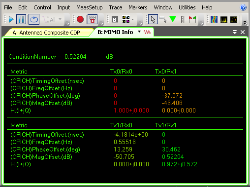
"Num Tx" (hidden value accessible from COM API) indicates the number of transmit antennas processed for the measurement. This will match the user parameter "Number of Tx Antennas". If this value is "1", then the remainder of the trace will have "N/A" in place of values, and a "NO DATA" trace indicator, because MIMO analysis is not performed.
"Num Rx" (hidden value accessible from COM API) indicates the number of receiver antennas (number of input channels used by the VSA for the measurement).
"Condition Number" indicates the condition number of the MIMO channel matrix. This is a single value indicating the correlation of the MIMO channel, assuming static fading.
(CPICH) Timing Offset is the detected timing offset of the CPICH channel for each path. The Timing Offset is computed assuming the transmitter is time synchronized between antennas. Therefore both Tx0/Rx0 and Tx1/Rx0 are a reference value, and the value for Tx0/Rx1 and Tx1/Rx1 will be identical.
(CPICH) Freq Offset is the detected frequency offset of the CPICH channel for each path. The Freq Offset is computed differently depending on the MimoFreqOffsetModel property. If "Rx" model is selected, the measurement assumes just the transmitter is frequency locked between antennas. Therefore both Tx0/Rx0 and Tx1/Rx0 are a reference value, and the value for Tx0/Rx1 and Tx1/Rx1 will be identical. Otherwise if "Tx" model is selected, the measurement assumes just the receiver is frequency locked between antennas. Therefore both Tx0/Rx0 and Tx0/Rx1 are a reference value, and the value for Tx1/Rx0 and Tx1/Rx1 will be identical
H is the estimated MIMO channel matrix.
(CPICH) Phase Offset and (CPICH) Mag Offset are computed based on the H result described above. The Tx0/Rx0 path is assumed to be the reference with 0deg Phase Offset and 0dB Mag Offset.