4DTF (Distance to Fault) Measurements
CAT Mode Distance to Fault (DTF) measurements are generally used to locate problems, or faults, in a length of cable or transmission line. In this chapter, the cable to be tested is referred to as the DUT (Device Under Test).
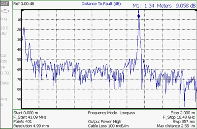
Settings that are NOT unique to DTF measurements are documented in the CAT Mode Chapter 3, “CAT (Cable and Antenna Test) Mode.”
Optional settings
Trace Math is NOT available in DTF Measurements. |
Before starting, you may need the following:
—Jumper cable or adapter to connect the beginning of the DUT to the FieldFox.
—LOAD with correct connector type and gender to terminate the end of the DUT (if possible).
—The known length and cable type of the DUT. If the cable type is not known, then the Cable Loss (dB/Meter) and Velocity Factor of the DUT are required.
1.Connect any necessary jumper cable or adapter to the FieldFox RF OUT port. Do NOT connect the DUT.
2.Press Preset then Preset to return the FieldFox to the default settings.
3.Then Mode then CAT.
4.Then Meas 1 then DTF.
5.Press Freq/Dist, then Stop Distance and enter the length of the DUT. You can optionally set the Start Distance
6.Press Cal 5 and follow the Cal prompts. Learn all about Calibration in “How to Perform a Calibration” on page 134.
7.Disconnect any components or antenna that should NOT be measured and connect a LOAD at the end of the DUT.
8.Press Meas Setup 4 then DTF Cable Specifications.
9.Either press Edit/Save/Recall Cables then Recall Cable, or directly enter the Velocity Factor/Cable Loss of the DUT using the Velocity Factor and Cable Loss keys.
10. Connect the start end of the DUT to the FieldFox.
11. Press Meas Setup 4 then Settings then Next Page. If the Alias-free Range setting is False, then you may see Alias faults on the screen. Learn more on page 79.
DTF Measurement Settings
You can set and view all of the DTF settings, including some calculated values, on the DTF Settings table. Learn about the calculated values in “Calculated DTF values” on page 78.
How to make settings on the DTF settings table
1.Press Meas Setup 4 > Settings.
2.Press Next Page and Previous Page to view all settings.
3.To change a setting:
—Use the  arrows or rotary knob to highlight a setting.
—Numeric settings can be changed by pressing numbers using the numeric keypad. Then press Enter or select a suffix if available.
—Other settings require you to press Edit, then press a softkey to change the value.
—When finished changing a value, press Done Edit.
4.Press Dock Window to relocate the Settings table to a position relative to the trace window. The setting persists through a Preset. Choose from the following:
—Full (Default setting) Only the Settings table is shown on the screen. The trace window is temporarily not shown.
—Left The Settings table is shown to the left of the trace window.
—Bottom The Settings table is shown below the trace window.
5.When finished changing ALL settings, press Done to save your settings.
You can select from 3 different DTF Formats.
1.Press Measure 1
2.Then choose from:
—Distance to Fault (dB) Faults are displayed on the Y-axis in return loss format, expressed as a positive number in dB.
DTF (VSWR) Faults are displayed on the Y-axis in SWR. Learn more about SWR at the FieldFox Supplemental Online Help at: https://rfmw.em.keysight.com/wireless/helpfiles/FieldFoxOnlineSupplementalHelp/Home.htm.
—More then DTF (Lin) Faults are displayed on the Y-axis in linear (unitless) format.
In DTF measurements, you set the physical length of cable or other device to be tested. The FieldFox calculates the frequency range of the measurement from this distance. The longer the cable to be tested, the lower the frequencies that are used. You can also set the frequencies manually using the Frequency Mode [Bandpass] setting.
How to set Start and Stop Distance
—With a DTF measurement present, press Freq/Dist.
—Then choose from the following:
—Start Distance Enter a value using the numeric keypad, the arrows, or the rotary knob, then Enter. By default, the Start Distance is set to 0 Meters. This means that the measurement will display faults starting at the point at which calibration standards are connected.
—Stop Distance Enter a value between the start distance and 5 km (or 16,404 ft.) using the numeric keypad, the arrows, or the rotary knob, then Enter.
All DTF measurements are made with frequency settings and, using Inverse Fourier Transform (IFT), the time and distance to faults are calculated.
| The start and stop frequencies for the measurement are always annotated on the screen below the start and stop distances. |

How to set Frequency Mode
With a DTF measurement present:
1.Press Meas Setup 4 > Freq Mode
2.Choose one of the following:
—Lowpass The frequency range of a DTF measurement is set automatically based on the Start and Stop Distances. Use Lowpass mode when the DUT is a cable ONLY.
—Bandpass (Default setting) The frequency range of a DTF measurement is set manually. Use Bandpass mode when the DUT contains a diplexer or other filtering device which does not pass some frequencies.
Typically, you will set the frequency range of the measurement to the passband of the filter. However, you may also want to test the ability of the filter to reject unwanted frequencies. In this case, set the frequency range to include those frequencies which the filter may not be adequately rejecting.
How to manually set Frequencies in Bandpass Mode
1.Press Freq/Dist
2.Then Min Start Freq and type the start frequency to use for the DTF measurement.
3.Then Max Stop Freq and type the stop frequency to use for the DTF measurement.
OR
1.Press More
2.Then Max Freq Span and type the frequency range to use for the DTF measurement.
3.Then Center Frequency and type the center frequency of the range to use for the DTF measurement.
When the DTF frequencies are set manually, they may not be the optimum frequencies for measuring the distance to fault. The distance may no longer be alias-free. Learn more about alias-free range on page 79.
These settings specify the minimum and maximum frequencies to be used for the DTF measurement. These exact frequencies may not be used, but a narrower frequency range may be used that will still pass through the bandpass filter.
When a Return Loss & DTF measurement is present, this setting allows you to have different frequency ranges for each measurement. Learn more in “Coupled Frequency” on page 64.
Cable (Correction) Specifications
By default, the FieldFox does NOT correct DTF measurements to account for the inherent loss of a cable. However, to make more accurate DTF measurements, the Cable Loss and Velocity Factor values should be considered.
| The following describes Coax Media type. However, you can create or edit Waveguide Media Standards. Learn how in “Waveguide Calibrations” on page 147. |
About Velocity Factor and Cable Loss
—Velocity Factor is a property of the physical material of a cable. A VF of 1.0 corresponds to the speed of light in a vacuum, or the fastest VF possible. A polyethylene dielectric cable has VF = 0.66 and a cable with PTFE dielectric has VF = 0.7.
—Cable Loss is specified in dB/meter. In addition to the length of the cable, loss is also directly proportional to the frequency of the signal that passes through the cable.
The following is an example showing how DTF cable correction works:
The DUT is a 100 meter transmission cable. The Cable Loss value is 0.1 dB/meter. This means that a signal traveling ONE WAY through the cable will lose 10 dB of power (100 m * 1dB/m). Because the FieldFox performs this measurement with 1 port, the test signal travels down the cable and then back, for a total loss of 20 dB.
After a calibration has been performed, for the purpose of illustrating this point, connect an OPEN to the end of the cable – a maximum-sized fault - for 100% reflection of the 300 MHz test signal.
Without compensation for the loss of the cable, a –20 dB response would be visible at 100 meters, which is the OPEN at the end of the DUT. This is from 10 dB of loss through the cable in each direction.
With compensation for the loss using the manufacturer’s specification, the FieldFox compensates the trace as though the signal traveling through 100 meters was increased by +20 dB. Therefore the response will show 0 dB for 100% reflection.
How to enter Cable Loss and Velocity Factor
Cable Loss and Velocity factor can be entered using one of the following methods:
—Manually enter cable loss and velocity factor for the measurement.
—Select or create a cable file which contains the cable loss and velocity factor.
With a DTF measurement present:
1.Press Meas Setup 4 > DTF Cable Specifications.
2.Select Cable Corr
—Auto Use Cable Loss and Velocity Factor values from a Cable file. See “How to Edit a Cable File” on page 76 and “How to Save or Recall a Cable” on page 76 below. This will overwrite a manually-entered value.
—Man (Default setting) Manually enter a value for Cable Loss and Velocity Factor.
3.Then:
—Velocity Factor Using the numeric keypad, enter a value between 0.01 and 1. Then press Enter.
—Cable Loss Using the numeric keypad, enter a positive Cable Loss value in dB/m, then press Enter.
The FieldFox includes many predefined cable files with the manufacturer’s specifications. You can edit these files or create new cable files using the following procedure or using the FieldFox Data Link Software.
The Cable correction data survives a Mode Preset and Preset.
With a DTF measurement present:
1.Press Meas Setup 4 > DTF Cable Specifications > DTF Cable Specifications
2.Press New Cable then Yes to clear all data from the existing DTF Cable table and reset header information to default settings.
3.Then Edit Cable to open the Cable Editor.
4.Then use the arrows to select a field,
—When editing Cable Description information, press Edit then modify the selected field using the FieldFox labeler.
—When editing Frequency/Loss pairs, enter numbers using the numeric keypad, then select a frequency suffix. Then Enter. Learn more about “How the Freq/Loss pairs are applied” on page 77 below.
5.Optionally choose from the following:
—Previous / Next Page Quickly scrolls through pages of Freq/Loss data.
—Add Data Add a blank Freq/Loss pair to the table,
—Delete/Clear then:
—Delete Row Remove the selected Freq/Loss pair from the table.
—Clear All then Yes. Remove all Freq/Loss pairs from the table and resets header information
6.Press Done to close the Cable Editor.
—Press Save Cable to saves your changes to the specified Storage Device. Enter a filename using the FieldFox labeler (learn more on “How to use the FieldFox labeler ” on page 916). Learn more about Cable files below.
—Press Recall Cable to load a Cable file from the specified Storage Device
—Storage Device Changes the device used to save or recall Cable files. This is a different setting from the Save/Recall Storage Device setting. Choose from Internal (default setting), USB (must be connected) or SD card.
About Cable files
—Cable files are saved to, and recalled from, the Cables folder. If the folder does not already exist on a USB or SD card, it is created automatically before storing the file.
—Cable files are stored as *.xml files. Existing cable files that are preloaded into the FieldFox firmware can be overwritten. Your edited file will NOT be overwritten when firmware is updated.
—To DELETE a Cable file, use the Manage Files feature. Learn more in “Manage Files” on page 922.
How the Freq/Loss pairs are applied
When the cable file contains one Freq/Loss pair, that correction value is applied to the entire displayed frequency span.
When the cable file contains two or more Freq/Loss pairs, the Loss value that is used is interpolated from the Freq/Loss pairs and the DTF center frequency. For example, using a cable file with the following Freq/Loss pairs:
The center frequency for the measurement is determined from the calculated (Stop – Start) frequency values (seen on the second page of DTF Settings):
The Loss value for the measurement is interpolated from the Freq/Loss pairs at the Center Freq:
The correction for loss at 5 meters in one direction: 0.18 dB/m * 5m = 0.9 dB.
All DTF measurements correct for loss for travel down the DUT and back, so double the correction: 0.9 dB * 2 = 1.8 dB.
Window settings provide the ability to choose between optimizing DTF measurements for resolving closely-spaced faults or for the ability to measure low-level faults.
How to select Window settings
1.Press Meas Setup 4 > Settings
2.Then press arrows to move to the Window row.
3.Then press Edit.
4.Then press Window and choose from the following:
—Maximum (Maximum – Optimized for dynamic range) the noise floor is lowered to provide the ability to measure low-level responses. (Default setting)
—Medium – Compromise between Minimum and Maximum window settings.
—Minimum – Best Response Resolution, providing the ability to resolve between two closely-spaced responses.
5.Then press Done Edit.
6.Again press Done.
The DTF Units setting is available ONLY on the DTF Settings table.
By default, X-axis units for DTF measurement settings are displayed in Meters.
1.With a DTF measurement present, press Freq/Dist.
2.Then More then Distance Unit m feet.
3.The current selection is underlined m (meters) Feet.
Press Next Page on the DTF Settings Table to view the following calculated Values noted on the FieldFox screen with c - <setting>
Start Frequency – Start frequency that is used to calculate DTF.
Stop Frequency – Stop frequency that is used to calculate DTF.
Range Resolution. Indicates the accuracy of the distance to fault measurement. For example, with range resolution of 500 mm, if the distance to fault is 10 meters, this value could be inaccurate by +/- 500 mm or between 9.5 to 10.5 meters. This value is calculated from frequency span / resolution (points).
Response Resolution, not displayed, indicates the distance that could be between two faults and still show as separate faults. Learn more in “Window Settings” on page 78.
Maximum Distance. The distance that could be viewed with the current settings. Defined by: Vf*c*Points/(2*Bandwidth) where:
—Vf = velocity factor
—c = speed of light
—Points = resolution
—Bandwidth = frequency range
Alias-free Range (On/Off)
—On = No Alias images
—Off = Alias images may appear in the response.
An alias fault is not a true device response. An alias fault appears because of the method used to convert frequency to time.
On the DTF Settings page (above) the c - Alias-free Range = Off setting indicates alias images MAY appear on the screen.
Shorter stop distances (less than 10 meters) and a higher resolution (1001 points) will be more likely to result in Alias-free Range = Off.
When the Alias-free Range = Off, the following procedure will help to determine if a response is true or an alias response:
1.Put a marker on the response in question and note the distance to the fault.
2.Change the start or stop distance.
A true fault response will not move in distance. That is, if a true fault is present at 10.3 meters, changing the stop distance from 15 m to 20 m will not move the fault; the fault will remain at 10.3 meters. However, an alias response will appear to move.
An unterminated cable (with NO perfect load at the end) will show faults that appear to be beyond the end of the cable. These are NOT alias faults. These faults appear as the signal reflects off the open at the end of the cable and travels back down the cable toward the connection at the FieldFox. Re-reflections are measured at the FieldFox as mirror images of the original faults. The largest fault is the open end of the cable. To avoid confusion, set the Stop distance shortly after that fault.