
Source Only calibration optimizes the signal at a specified center frequency, amplitude, and analyzer input range, independent of analyzer calibration.
Since source calibration requires the use of analyzer hardware to receive and process the generated signal, it is best to first calibrate the analyzer hardware so you can use the analyzer corrections during the source calibration to eliminate analyzer impairments. If you do not have a U9391 comb generator (required for analyzer calibration), you can still greatly improve signal quality by performing a Source Only Calibration with Analyzer Corrections Disabled.
Start the Calibration Wizard.

Set the Type of Calibration to Perform to Source Only, then click Copy Current Operating Point to apply the system's current Frequency, Bandwidth, Source Amplitude and Analyzer Input Range to the calibration point.

You can define multiple calibration points and have the Calibration Wizard create a set of correction files in a single batch operation if you want to calibrate a variety of points to optimize for dynamic range or other conditions. See the Source Calibration part of Step 9. Perform a Multi-Point (Batch) Calibration for details on batch calibration.
Make sure Analyzer Corrections is set to Disabled.
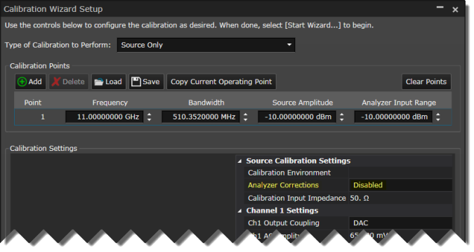
Click the Start Wizard button.

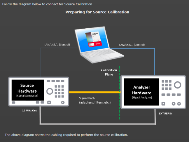
Connect your system as shown in the diagram. Verify your connections, then click Next to perform the source calibration.
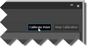
Click Calibrate Point.
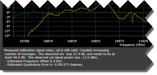
For source calibration, the Calibration Wizard performs a two-step process where the signal is first measured (yellow plot). The second pass (green plot )is a signal that is compensated for impairments based on the first measurement. There is also an ideal signal (gray plot) that appears briefly but is covered by the optimized signal.
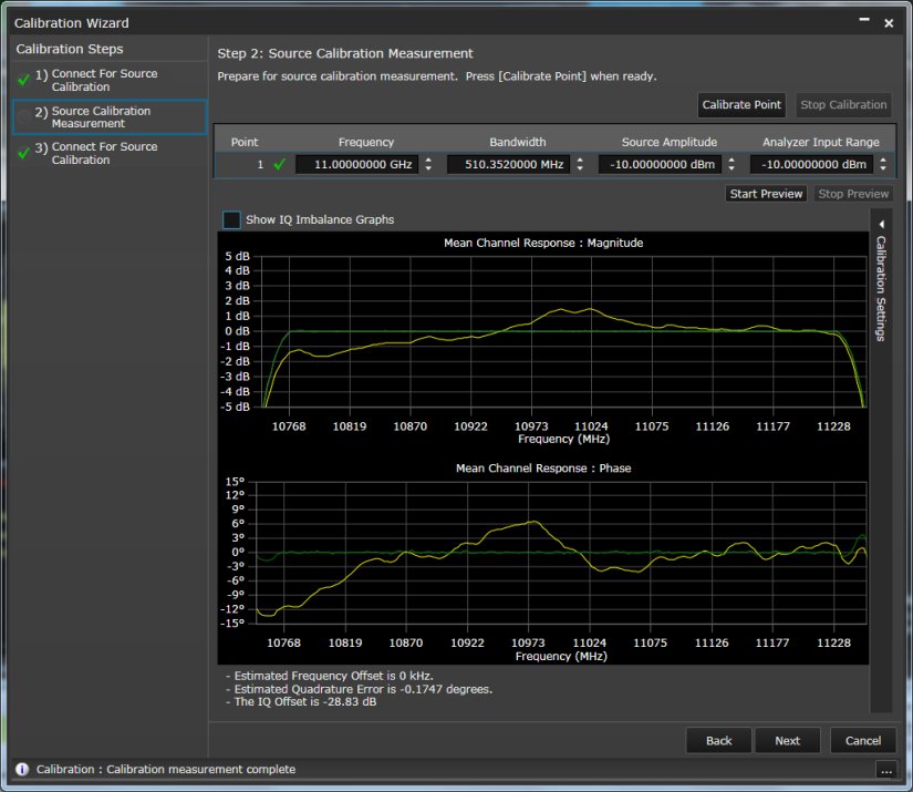
In addition to the channel response before and after magnitude and phase plots, there is summary result information below the plots. If your signal is excessively noisy, you will see additional diagnostic feedback with the summary result information.
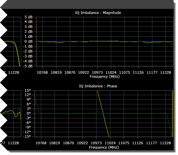
Click Show IQ Imbalance Graphs view.

In our example, our IQ cables are of unmatched length, resulting in IQ phase imbalance (yellow and blue plots) that's literally "off-the-charts." The flat green line at 0 degrees represents the compensated result after calibration.
Click Next. The Calibration Complete screen indicates the successful completion of the single-point calibration. It also lists the calibration files the Calibration Wizard created to correct for impairments in the connected measurement hardware.
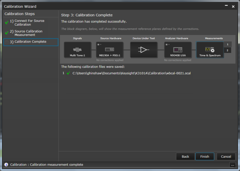
Click Finish to exit the Calibration Wizard and to apply the corrections to a custom IQ measurement.
If you wish to also learn about the recommended whole system source and analyzer calibration, click Next to Step 7. Perform a Source and Analyzer (Single-Point Only) . Otherwise, you can skip the next step and proceed to to Step 8. Apply the Corrections to a Custom IQ Measurement.