Option 002 is a separate software program that facilitates making reflectivity measurements using a fixture commonly referred to as an NRL arch (Naval Research Laboratory).
To use this option, click Arch Reflectivity Measurements on the Select Measurement Method dialog.
Many of the menu features are the same as the N1500A software. See Software Reference for a explanation of these common features.
Click Measure, then Define Measurement to setup the analyzer.
Click Measure, then Arch Calibration to calibrate the fixture.
Click Measure, then Trigger measurement to perform a measurement of the DUT.
Click Chart to make various settings for analyzing the measurement data.
The items in the Measure menu represents the only difference between the Option 002 software and the N1500A standard product.
Click Measure to see the following choices:
Set Frequency (separate topic)
Triggers a measurement ONLY if a Calibration has already been performed.
Allows many of the selections to be made for a variety of common coaxial and waveguide transmission lines.
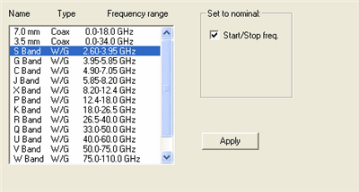
Select the transmission line of interest, check the desired parameters and click Apply.
The appropriate items will be changed.

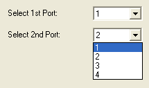
This dialog allows you to use any of the available analyzer ports for the 2-port measurement.
Select a port number for each of the 2 ports.
This menu, unique to Option 002, guides you through the following steps to calibrate the fixture.
An Arch Calibration requires a full two-port calibration be performed at the end of the cables used to connect the network analyzer to the antennas.
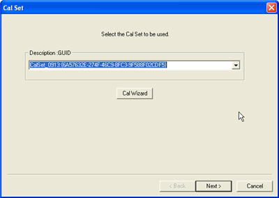
Select EITHER a Cal Set or Cal Wizard:
Click Cal Wizard to perform a new calibration on the connected instrument. Once th new calibration is complete, the new Cal Set appears in the above dialog.
Select an existing Cal Set stored in the analyzer, then click Next >. A message may appear if the settings in the instrument do not match the settings in the select Cal Set. Select a different Cal Set.
After the S-parameter portion of the calibration is performed, select the Time Domain parameters for the Freespace portion of the calibration.
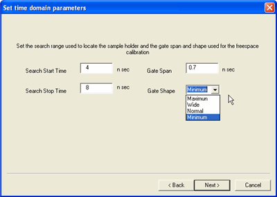
This dialog box allows you to set the time domain parameters to be used during the remainder of the calibration.
Search Start and Stop Times The metal time domain response occurs between these times.
Gate Span Select the amount of time to be gated into the measurement.
Gate Shape Defines the filter characteristics of the gate function. Choose from Minimum, Normal, Wide, Maximum. Learn about Gating in the PNA. Requires an internet connection.
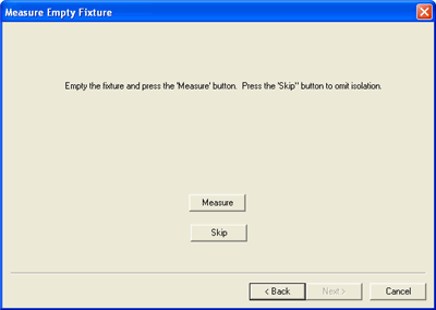
Place the metal plate in the fixture.
Skip - Omits the isolation portion of the cal. If you measure the empty fixture make sure nothing is in the volume that the metal plate occupies.
Measurement - Make a measurement.
Click Re-Measure to remeasure the standard.
Otherwise, click Finish.
The calibration error terms are calculated and applied.
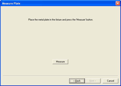
Place the plate in the fixture and press Measure.
Some fixtures employ antennas with two connectors.
When NOT checked, the calibration and measurement will be made assuming the antenna has only one input or the second input is not being used.
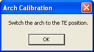
When checked, the calibration and measurements will be made using both inputs. The use of the terms TE and TM are somewhat arbitrary. A message like the following will prompt you to switch the input connector.
