Equipment Used
Probe Stand, N1501A-002
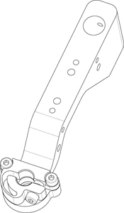
Mounting Bracket (silver colored with two large thumb screws), included in N1501A-003
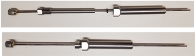
Dielectric Probe, N1501A-101
Cable, Recommended N1501A-201 or N1501A-202
Adapters may be needed to make connections depending on your configuration. See Adapter Selection Guide
Connections
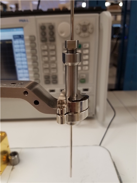
Connect Mounting Bracket to Probe Stand by slipping the opening over the Probe Stand rod, and tightening the two large thumb screws in the back
Connect Probe to Mounting Bracket
Remove large knurled nut from connector end of Probe
Guide probe connector up through hole in Mounting Bracket and reconnect large knurled nut to hold it in place.
Connect Cable to Probe.
Connect other end of Cable to analyzer