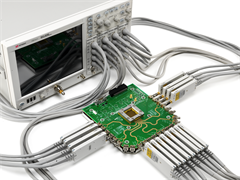
Beginning with PLTS 2016, TDR calibration and measurements can be set up using the TDR Wizard on DCA oscilloscopes with FlexDCA remote access software installed. In addition, the latest TDR modules are supported including the N1055A remote heads, which provide up to 16 channels and place the signal close to the DUT to minimize stimulus degradation.
The TDR Wizard can be started in several ways:
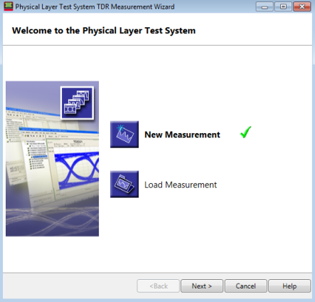
When PLTS is first started and a DCA is selected.
When a new measurement is initiated. Click File, then New or click the new file icon 
By clicking Tools, then Launch Startup Wizard.
|
Click one of the following: The selected choice has a
|
|
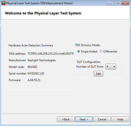
Hardware Detection, TDR Stimulus Mode, and DUT Configuration dialog |
|
This dialog box is displayed when New Measurement is selected.
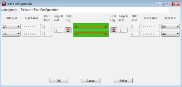
Detect the PLTS Hardware SummaryThe left side of the Welcome dialog shows the connected TDR model number, address, serial number, and the firmware revision. TDR Stimulus ModeSingle Ended - Choose for single-ended DUT ports. The number of single-ended DUT ports can be 1, 2, 4, 8, 12, or 16. The number of DUT ports cannot be larger than the number of hardware ports. Port 1 only appears when the stimulus mode is single-ended. For example, if the hardware has 8 ports, then in single-ended stimulus mode 1, 2, 4, and 8-port DUTs can be measured. If the hardware has 16 ports, then 1, 2, 4, 8, 12, and 16-port DUTs can be measured. Differential - Choose for differential DUT ports. For example, if the hardware has 8 ports, then in differential stimulus mode 2, 4, and 8-port DUTs can be measured. If the hardware has 16 ports, then 2, 4, 8, 12, and 16-port DUTs can be measured. DUT ConfigurationNumber of DUT Ports - Choose the number of DUT ports. DUT ports refers to the number of single-ended ports. To see the following dialog, click the Edit button. This dialog is used to map between TDR channels and DUT ports for single-ended and differential stimulus modes. Some ports may be disconnected. Clicking the Edit button displays the following dialog for mapping:
|
|
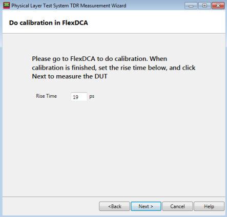
You must go to the DCA to perform calibration. Rise Time - Sets the rise time of normalized measurements in picoseconds. This is a function of normalization and is available to only the Keysight 86100-based TDR systems. Note: Set the rise time after calibration is finished. |
|
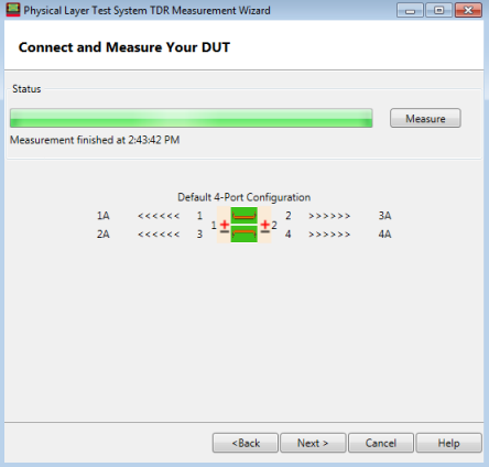
When you click on the Measure button, time domain waveforms and S-parameters are transferred from the DCA to the PLTS.
|
|
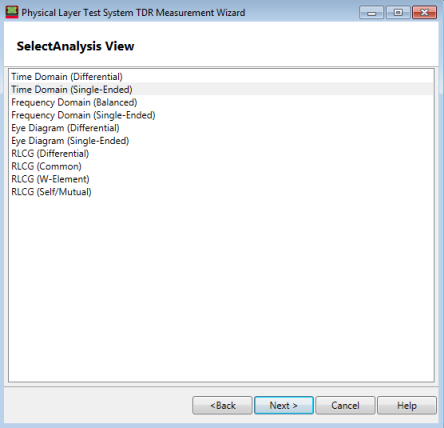
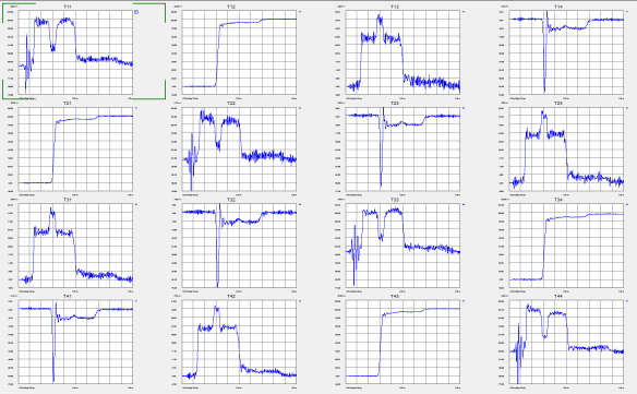
Selecting an analysis view displays the measured parameters. The following is an example of time domain (single-ended) measured parameters.
|