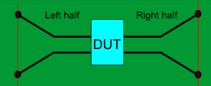
Test fixture
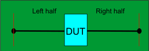
2X Thru standard
OR

Left or Right halves of 2X Thru standard


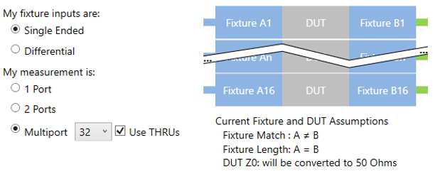
Supports 1-port, 2-port, and multi-port single-ended DUT configurations.
When used with a multi-port DUT configuration, the trace coupling is not removed.
This feature requires Advanced Calibration (5xP) PLTS license.
In this topic:
AFR has the following enhancements with the PLTS 2016 release:
AFR has the following enhancements with the PLTS 2018 release:
|
Fixtures are often used for DUTs that have non-coaxial interfaces. This feature allows you to mathematically remove, or de-embed, a characterized test fixture from displayed measurement results of the test fixture and DUT.
Tip: If you do NOT have a 2X Thru calibration board built, then try the 1-port AFR method first and use the fixture with an open at the desired reference plane as a start. This is an extremely fast and easy test to see if the fixture open works well or not. If the fixture open radiates too much (like a SMA male connector
would), then the next step is to try a 1-port AFR with a short
at the fixture output. These are both very easy to test without
building special calibration standards. If neither of these two
methods work, then the best practice might be to build a 2X Thru
standard and use following the 2X Thru AFR method. |
Before starting the AFR process, Perform a calibration at the connectors of the test fixture (red lines in images below).
The AFR Wizard will guide you through these steps:
Describe your fixturing situation.
Specify how the Thru fixture characterization will occur.
Perform characterization.
Remove the effects of the test fixture, leaving ONLY the displayed results of the DUT.
Touchstone files are saved that characterize the two halves of the test fixture.
It may be possible to characterize up to 64 1-port fixtures. In this case, 1x or 2x Thru standards are not necessary.
Must
have a test fixture and either a 2X Thru OR Left and Right Thru halves,
all shown below.
NOTE: The fixture itself can
be used as a left or right Thru half.
For 1-port DUTs, only a Left OR Right Thru half is required.
Both the Test fixture and Thru are made of the exact same medium; preferably fabricated ON the same piece of medium.
Test fixture |
|
2X Thru standard
OR |
|
Left or Right halves of 2X Thru standard |
|
Supports 1-port, 2-port, and multi-port single-ended DUT configurations. When used with a multi-port DUT configuration, the trace coupling is not removed. |
|
Test fixture |
|
2X Thru standard
OR |
|
Left or Right halves of Thru standard |
|
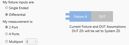
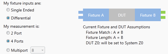
Differential configurations also remove the effects of coupling between the differential traces. |
|
With a calibrated measurement of the DUT in the test fixture present:
Click Utilities,
then Automatic Fixture Removal,
then Wizard or click on the Automatic Fixture Removal Wizard
icon (![]() ).
).
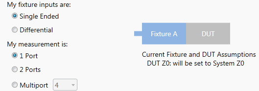
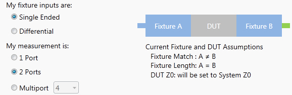
Note: These dialog boxes show images for a Single ended DUT, but Differential works exactly the same, only with Differential S4P files. For best results, follow the AFR Wizard tabs from steps 1 through 5 by either clicking Next > or clicking the tabs. In this section: 1. Describe FixtureThe choices that you make in the dialog are reflected in the diagram and text. The version number for AFR is shown in the upper-left portion of the dialog and is added to the AFR extracted touchstone file. This information helps to determine which algorithm was used. 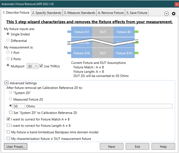
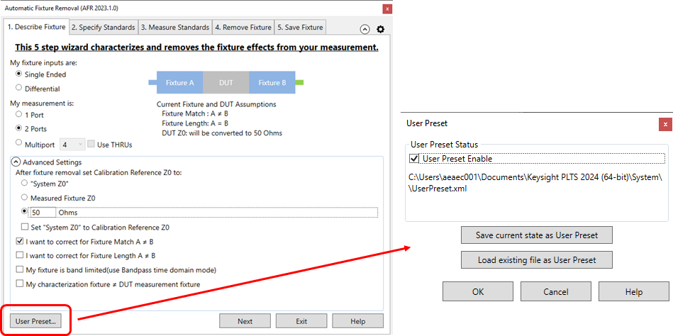
My fixture inputs are:
My measurement is (Single Ended):
My measurement is (Differential):
Advanced Settings (click ^ to show and hide)After fixture removal set Calibration Reference Z0 to: (Choose one of these settings)
Note: Changing the System Z0 setting does NOT change measured S-parameter data. Changing the port impedance setting WILL change the measured S-parameter data. For additional technical detail on non 50-ohm AFR applications, see this white paper (Internet connection required).
Select all that apply:
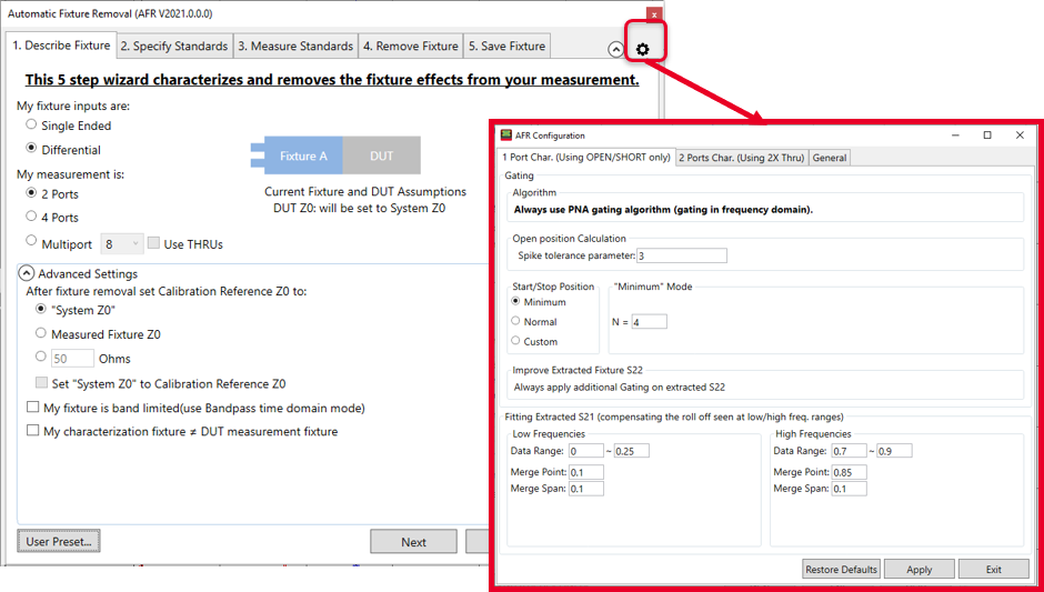
The AFR Configuration dialog can be launched by clicking on the gear icon (shown below) or by using the AFRCfg.exe application located in the directory where the PLTS application is stored (the default is C:\Program Files\Keysight\PLTS20xx). Double-clicking this file opens the AFR Configuration dialog. The AFR Configuration dialog has three tabs:
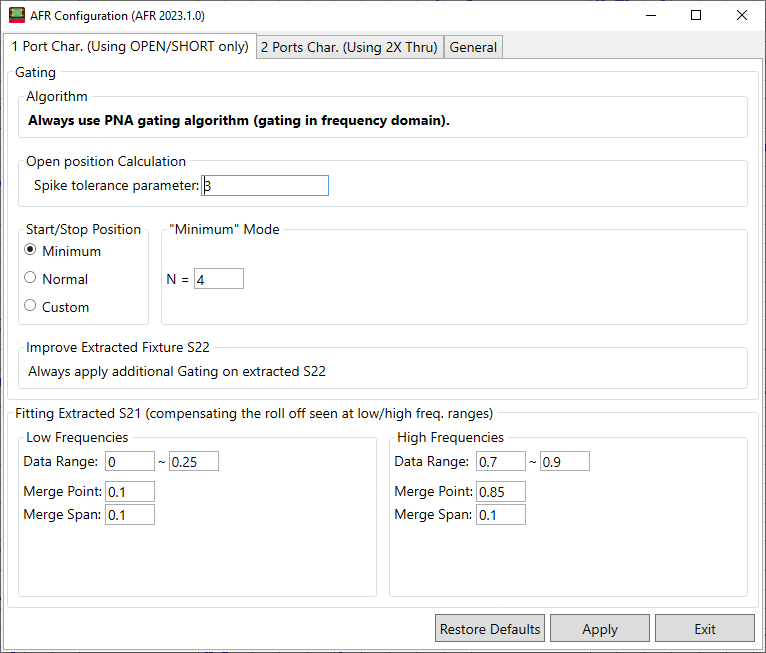
1 Port Char. (Using OPEN/SHORT only) Access the following settings in the 1 Port Char tab of the AFR Configuration dialog.
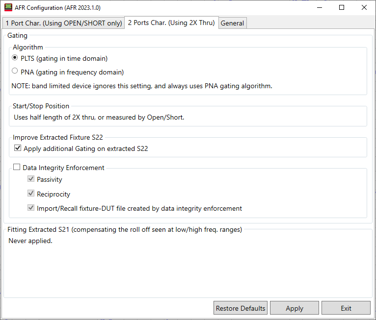
Access the following settings in the 2 Ports Char tab of the AFR Configuration dialog.
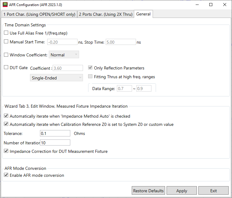
Access the following settings in the General tab of the AFR Configuration dialog.
Set manual time domain start and stop settings for corner cases shown under Time Domain Settings. Use Full Alias Free 1/(freq.step) - Check to set the stop time of impedance trace from 1/(2*freq.step) to 1/(freq.step) on dialogue Measure Fixture Impedance TDR data.
Manual Start/Stop Time - Check to set the manual start/stop time of impedance trace on dialogue Measure Fixture Impedance TDR data.
Window Coefficient - Check to use the manual window type. DUT Gate Coefficient - Check to use DUT gate coefficient settings. Select Single-Ended or Balanced. Only Reflection Parameters - Check to apply DUT gate on reflection parameters only. Fitting Thrus at high freq. ranges - Check to compensate for roll off at high frequency range. Data Range - Sets the data range. Merge Point - Sets the merge point. Merge Span - Sets the merge span. The Tolerance (in ohms) and Number of Iterations can be set under Wizard Tab 3, Edit Window, Measured Fixture Impedance Iteration. Also, two conditions for automatic iterations can be enabled via checkbox:
Also, check the Automatically Iterate when Calibration Reference Z0 is set to System Z0 or custom value box to automatically iterate in that condition. Fine-Tune the Impedance Matching - Check to apply advanced algorithm to fixture impedance mismatching cases for better results. Impedance Correction for DUT Measurement Fixture - Check to correct the fixture impedance when the impedances of fixture and fixture-DUT don’t match. AFR Mode Conversion - AFR mode conversion will turn on or off automatically to make the AFR result more precise with non-single ended data. Checking In PLTS show menu item in the General tab will allow this dialog to be opened from within the PLTS screen by selecting Utilities -> Automatic Fixture Removal -> Advanced AFR Configure. This button opens the User Preset dialog where you can save, load, and enable your fixture settings as an AFR User Preset.
2. Specify Standards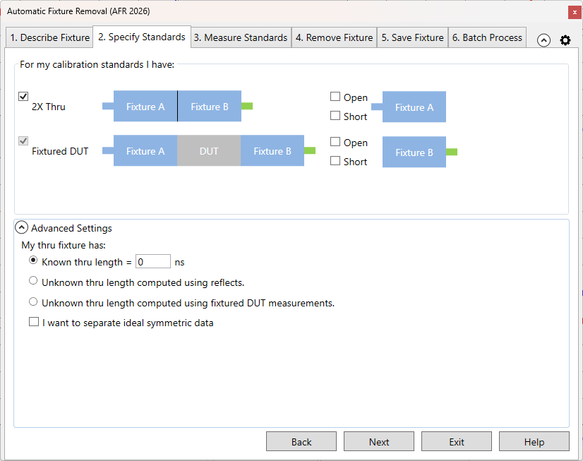
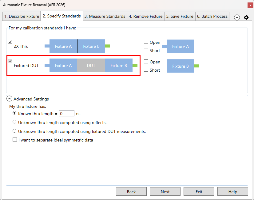
Selecting 2 single-ended ports, or 4 differential ports allows a 2X Thru choice.
Checking Use THRUs in the 1. Describe Fixture tab allows 2X Thru choice for a Multiport measurement.
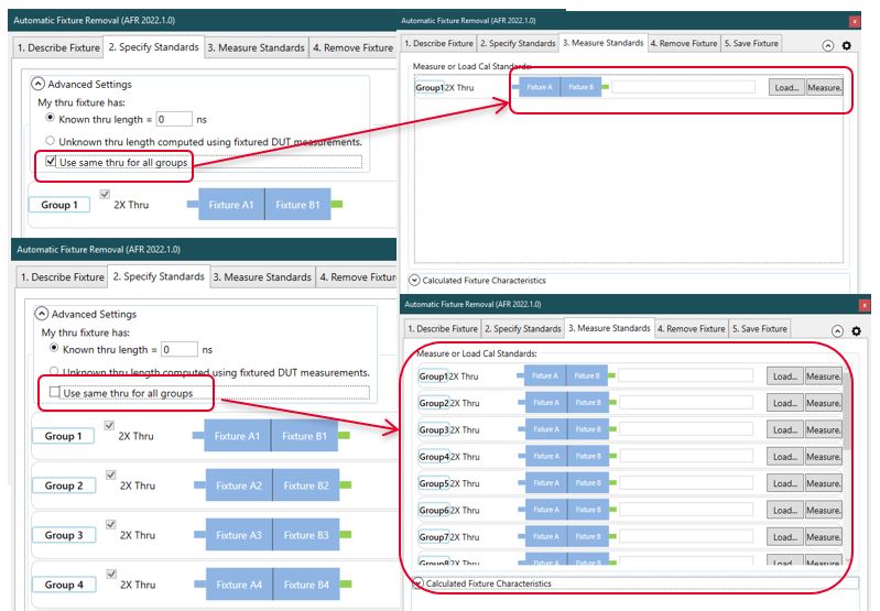
If the Use same thru for all groups is checked, only one cal standards need to Load or Measure instead of repeating the same steps for each group.
If My characterization fixture ≠ DUT measurement fixture is checked in the 1. Describe Fixture tab, the Fixtured DUT choice is displayed and checked.
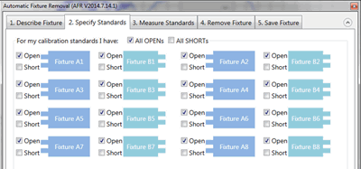
Otherwise, the fixture MUST be characterized using 1-port fixture measurements using either OPEN or SHORT terminations.
Note: The term 'Standards' is used here because this process can be thought of as the second calibration in a '2-tier' calibration process. The first tier of the calibration must already be performed (the VNA calibrated) before starting the AFR process. Another way of describing this step would be: "How will you be measuring or loading the characterization of the Thru standard?"
Notes:
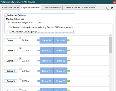
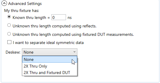
These settings are used to describe any ADDITIONAL length between the halves of the 2X Thru or added to either of the individual halves. If the electrical length of the Thru standard is identical to the test fixture, then make no changes to the default settings (Known length = 0).
My Thru fixture has:
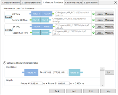
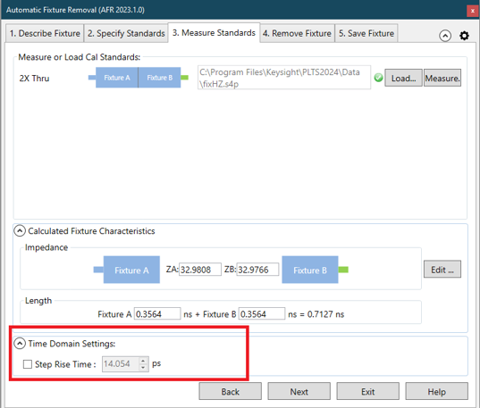
3. Measure Standards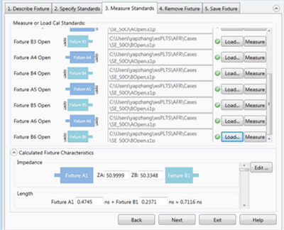
The following dialog is for Multiport 2X Thru measurements when Use THRUs is checked in the 1. Describe Fixture tab.
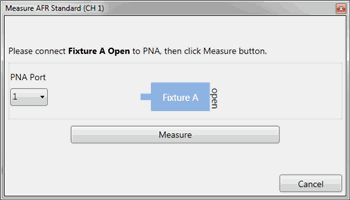
This step characterizes the 1X or 2X Thru standards. This is done by either performing measurements or by loading one or more *.snp files that describe the characterization of fixtures. Note: When loading standards from files, the typical system characterization impedance (Z0) value is used, which is 50 Ω. Click Measure to see the following dialog: For best results, the analyzer should be calibrated. Also, the measurement Start and Step frequencies should be equal. This is necessary for TDR measurements. Connect the specified standard at the PNA port. Then click Measure.
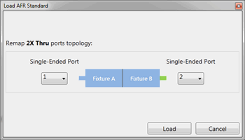
OR click Load and navigate to the *.snp file that describes the standard. For 2X Thru standards, the following dialog allows you to optionally remap the fixture ports.
Calculated Fixture CharacteristicsThe loaded or measured Impedance and Electrical Length of the fixture are calculated and displayed here. The preview button allows you to visualize the time domain characteristics of the fixture model that will be used for de-embedding. By using the editing features noted below, the output match, length, and impedance of the fixture model can be optimized. This allows flexibility for including or excluding physical characteristics such as excess inductance of plug fingers, excess capacitance of receptacle pads or any other anomalies not desired in the fixture model. This advanced feature should be used with care as misuse could cause passivity or causality errors in the resultant fixture model.
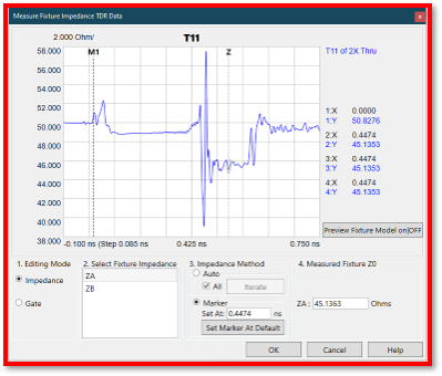
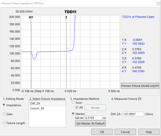
Click Edit to start the following, interactive Measure Fixture Impedance TDR Data dialog.
This dialog allows you to change the Impedance and/or Fixture Length of the saved *.snp data by moving a marker to the desired location on the TDR plot.
Editing Mode. (For 2X Thru, Fixture Length can NOT be changed.) Choose one or more of the following to edit the data in resulting *.snp files:
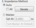
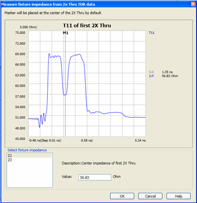
Select Fixture Impedance - Select the A or B fixture. Impedance Method - Select Auto then click Iterate to measure the fixture Z0 automatically and return fixture impedance back to 50 Ω. If more than one fixture impedance needs to be measured, check All to measure all impedances listed in Select Fixture Impedance. Select Marker to measure the fixture Z0 manually using the Z marker. The Set At field shows the X-axis position of the Z marker in ns. The Set Marker At Default returns the Z marker and fixture impedance to the default value.
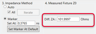
Measured Fixture Z0 - Shows the measured fixture impedance. When Marker is selected as the Impedance Method, this field displays the current Z marker value or a value can be entered directly in this field. When Auto is selected as the Impedance Method, this field displays the fixture impedance value that was found automatically after clicking the Iterate button. In Auto, moving the Z marker will not change this value. Diff: ZA: - Enter the AFR fixture impedance manually using the text box.
Fixture Length Editing Mode Select Fixture Impedance - Select the A or B fixture. Set Marker Position, Gate Position, or Fixture Length depending on the selected Editing Mode. Move the marker (M1, Gate flag, or diamond) to the desired response on the trace. Set At Default - PLTS chooses an appropriate length at which to set the initial impedance or length. Click to return the marker to this location.
Preview ON/off - Select Off, then ON to preview the new measurement. Click OK when finished. When saved, the new Impedance and Length results are copied to the *.snp files.
4. Remove Fixture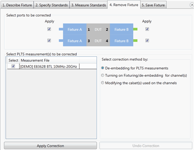
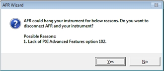
When using a PXIe system and the installed options are not sufficient to perform online characterization, the following dialog is displayed to prevent the system from hanging:
Note: First choose Select correction method, then make other selections, then click Apply Correction. While all three choices are valid, the most common choice is De-embedding for PLTS measurements. All three operations can be performed, but only one at a time.
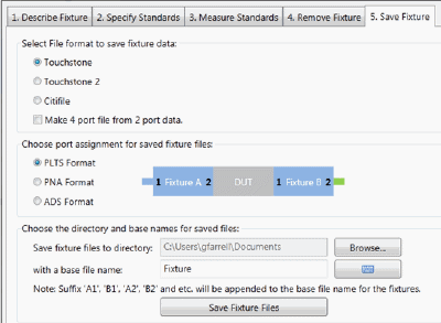
5. Save Fixture
Select File format to save fixture data:
Make 4 port file from 2 port data - Available ONLY when two single-ended 2-port fixtures are selected in the Describe Fixture tab (as in the above image).
Choose port assignment for save fixture files: The port assignments are interpreted differently when the file is opened in each program. Choose which program software you will be using to open the saved file: PLTS, PNA, ADS.
Choose the directory and base names for the saved files: Click Browse to navigate to a directory folder. With a base file name: The resulting filename will appear as follows (assuming a Touchstone format):
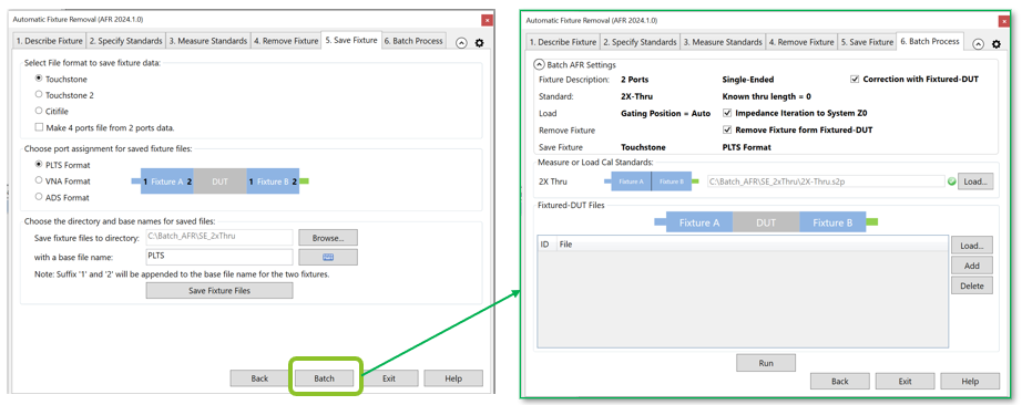
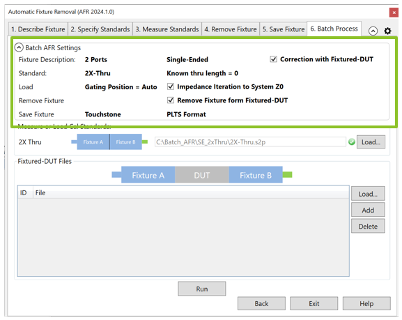
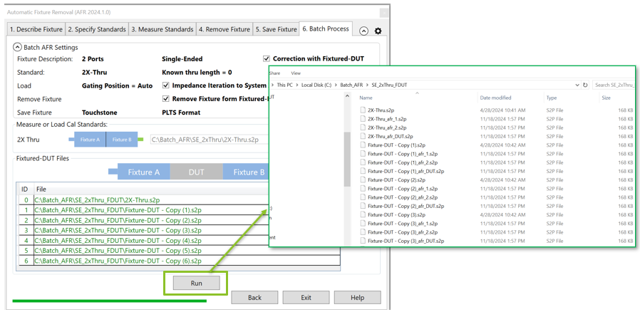
Click Save Fixture Files to save the files to the specified directory. 6. Batch ProcessThis feature is new with PLTS 2025. The batch process now supports multiport THRUs with PLTS 2026. Batch AFR facilitates the AFR when you have multiple fixtured-DUTs with the same 2x-Thru standards. You do not need to repeat the AFR wizard steps with batch process.
Batch AFR use the settings summary from previous AFR wizard steps.
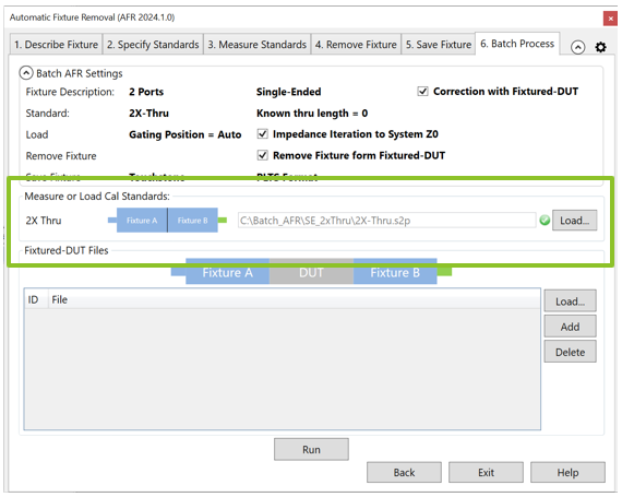
Measure or Load standards are the 2x-Thru standards of fixture. The default is the standard specified by previous AFR wizard. You can also load a different one by clicking the Load button.
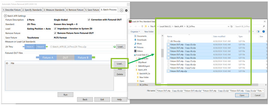
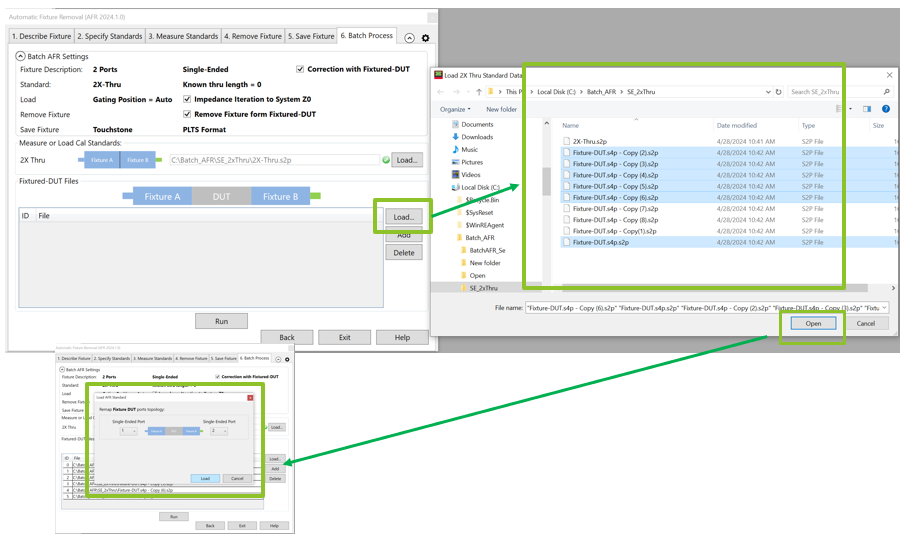
Click Load to import all the fixtured-DUT files.
Click Load to import all the fixtured-DUT files. All fixtured-DUTs will use the same topology.
Click Run. The batch process saves the fixture with appendix _afr_1 as left fixture , _afr_2 as right fixture, and _afr_DUT as de-embedded DUT.
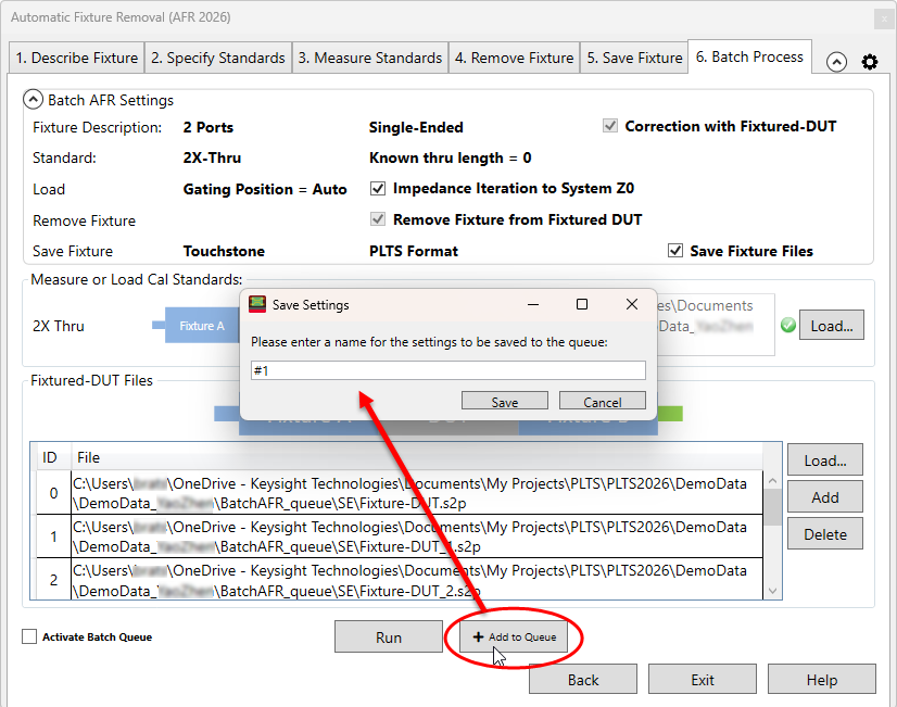
New AFR Batch Process features with PLTS 2026+ Add to Queue - Add the current batch configuration to the queue. A Save Settings dialog appears with a default name, representing its position in the queue. You can then create another batch configuration and save it to the queue.
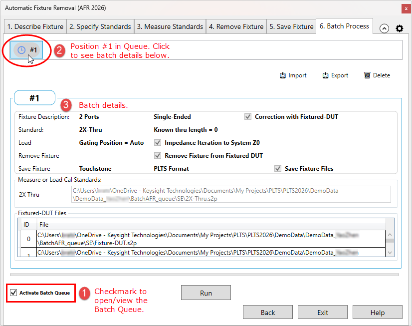
Activate Batch Queue - Click this checkbox to open/view the batch queue where your saved batch item is stored. Click the batch item-position-number button to view its details below.
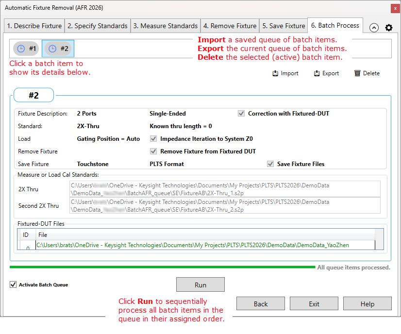
Import - Imports (recalls) a previously exported queue of batch items (*.xml) into the queue, overwriting the current queue of items. Export - Exports (saves) your current queue of batch items as an *.xml file. Delete - Deletes your currently selected (active) batch item from the queue. CAUTION: There is no Undo. Run - Sequentially processes all batch items in the queue in their assigned order. A progress bar is displayed during the operation.
|
This section discusses the legacy AFR User Interface. Unless you have a compelling reason to use these dialogs, the AFR Wizard has more functionality and is easier to use.
With a calibrated measurement of the DUT in the test fixture present:
Click Utilities, then Automatic Fixture Removal.
Then choose from:
Single-Ended
Differential
Note: The dialogs below show images for a Single ended DUT, but Differential works exactly the same, only with Differential S4P files.
Single-Ended / Differential AFR dialog help |
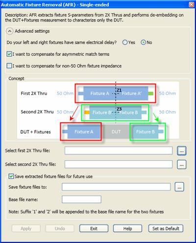
Single-ended dialog; left and right halves NOT the same delay Although Single-Ended is pictured here, the same dialog settings are used for Differential.
Do your left and right fixtures have the same electrical delay?
Select Thru File: Click
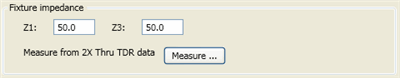
I want to compensate for asymmetric match terms Check when the left-half and right-half of the fixtures have different return loss values. Clear when they are identical. I want to compensate for non 50 ohm impedance When checked, the following appears on the dialog:
Specify the impedance for the left half (Z1) and the right half (Z3) of the fixture. Measure from 2X Thru TDR data Click Measure to load the *.S4P/*.S2P files that describe the 2X Thrus. The following dialog appears:
Save extracted files for future use
Save future files to:
Click Touchstone files of the Test Fixture are saved to the specified path and Base File Name:
Click Apply to remove the test fixture from the displayed measurement and optionally save files. Click Undo to revert to the displayed measurement of test fixture and DUT. Set as Default When clicked, the dialog settings are saved and populate the dialog next time it is started. |
Ideally, your symmetric 2X Thru is perfectly symmetric. Symmetry means S11 = S22, S12 = S21. After measuring the 2X Thru, you may want to compare those parameters to see how symmetric it is. You could manually add the S11 and S22 traces to the same plot. Or you could use Verify 2X Thru.
Click Utilities, then Automatic Fixture Removal, then Verify 2X Thru
Browse to any S2P file.
The utility opens the file in a pre-defined Template view with two plots, each plot with two traces. One with S11 and S22; the other with S21 and S12.
Visually compare the traces to determine the level of symmetry.
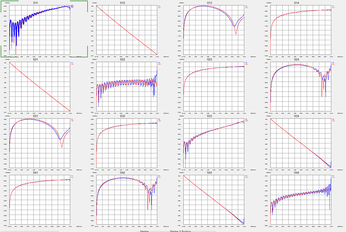
Beginning with PLTS2019, Mode Conversion implemented for improved AFR.
The following is a 4-port differential AFR result comparing ideal (red trace) to the AFR result (blue trace).
Without Mode Conversion in PLTS2018
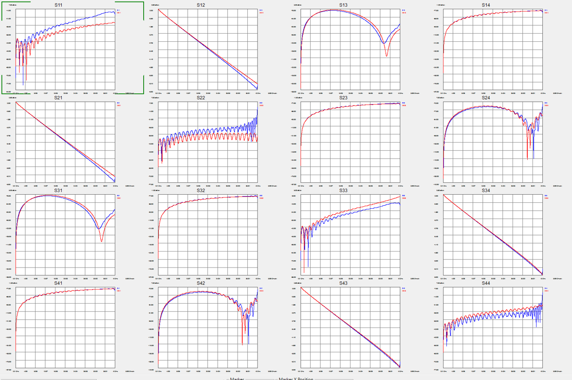
With Mode Conversion in PLTS2019