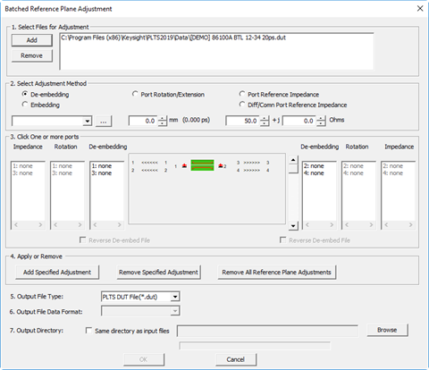
Select Adjustment Method
De-embedding / Embedding
De-embedding
mathematically REMOVES the effects of characterized device,
such as an adapter or fixture, from the measurement.
Embedding
mathematically ADDS the effects of the characterized device
to the measurement.
The device must
be already characterized and stored in an *.sNp file, *.cit file,
or *.DUT file. While measuring the device provides the most accurate
characterization, it may be difficult or impossible to perform
the measurement due to connectivity issues. In these cases, S-parameter
models may offer the best alternative. See also PLTS
Adapter Characterization tool. When using the De-embed
/ Embed feature, you must know the orientation of the ports as
the device was characterized.
Note:
Beginning with PLTS2016, 3-port DUT configurations are supported.
These are devices that convert a single-ended input to a differential
output.
Reverse
De-embed / Embed File Reverses, or 'mirrors' the device
port numbers as they are applied to the DUT port.
The following image shows a characterized
2-port device on the input and output of a 2-port DUT. The 2-port
file on the output is 'Reversed'.
Specify
location of the file to de-embed Click
... (browse) and to
navigate to your *.citi, *.DUT, or *.sNp
file, where N is the
number of ports that are characterized in the file. Select
Ports Select a port labeled 'none'
to which the specified file will be applied. The file is applied
to the ports below the selected port. For example, with a
6-port file to embed or de-embed, and port 2 is specified,
click Add Specified Adjustment
and the file is applied to ports 2,4, and 6. If there are
fewer DUT ports than ports in the specified file, an error
message is displayed. Apply
or Remove Click
to Add or Remove the adjustment to the specified ports.
Port Rotation
/ Extension
Allows you to move the calibrated
reference plane from the end of the test cable toward the DUT
to eliminate the effects of phase shift introduced by the addition
of adapters, fixtures, and probes. Port rotation does not correct
for additional loss and mismatch introduced by these items.
Specify Rotation Enter
the rotation in millimeters (mm). The equivalent time in picoseconds
(ps) is also displayed.
Enter
positive values to move the calibration reference plane
closer to the DUT. Enter
negative values to extend the reference plane away from
the DUT. You
may enter real numbers between -50000.0 mm and 50000.0
mm. Click
Up/Down arrows to change in 0.1 mm increments, or
enter values to 11 places to the right of the decimal
using the keyboard.
Select
Ports In the Rotation column, select a
port to receive the rotation value. Each port may be assigned
unique values. Apply
or Remove Click to Add or Remove the adjustment
to the specified ports.
Port
Reference Impedance
By default, all ports are set to 50 ohms impedance. This adjustment
mathematically transforms the measured data to show the performance
of the DUT in the specified impedance.
Specify the
impedance in ohms Enter real numbers between
0.0 ohms and 1000.0 ohms by 0.1 ohm increments using
the Up/Down arrows. You can enter values to 11 places to the
right of the decimal using the keyboard. Select Ports
In the Impedance column, select a port to receive the
Impedance value. Each port may be assigned unique values. Apply
or Remove Click
to Add or Remove the adjustment to the specified ports.
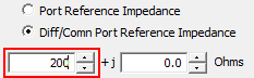
Diff/Com
Port Reference Impedance
The differential and common mode impedances are de-coupled and
can be changed independent of the single-ended impedance. Typically,
differential and common mode parameters are computed based on
the single-ended S-parameters. However, when the Diff/Com
Port Reference Impedance setting is selected, the single-ended
S-parameters will be computed based on the mixed mode parameters.
The following is an example showing how to set up, save, and
import mixed mode parameters.
Define mixed mode
parameters:
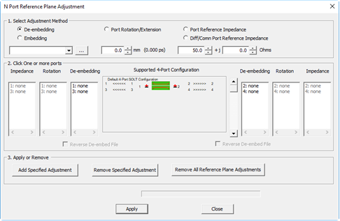
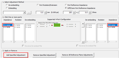
Select
Utilities >
N Port Reference Plane Adjustment.... The N Port
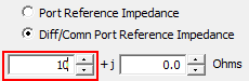
Reference Plane Adjustment dialog is displayed. Select Diff/Com
Port Reference Impedance. Enter the desired impedance value for
the differential impedance.
 In the Impedance columns, select the Dx: entries then click
the Add Specified Adjustment
button. The Dx:
impedance corresponds to the differential port.
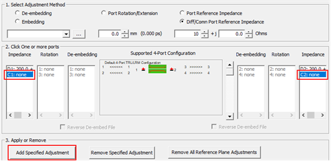
 Enter the desired impedance value for
the common mode impedance.
 In the Impedance columns, select the Cx: entries then click
the Add Specified Adjustment
button. The Cx:
impedance corresponds to the common mode port.
 Click the Apply
button to apply the settings or click the Remove
Specified Adjustment button to remove selected
settings or click the Remove
All Reference Plane Adjustments button to remove
all settings. Click the Close
button.
Save
Diff/Com Port Reference Impedance Settings:
Select
File > Export.... In
the Export Data dialog, select Mixed
Mode.
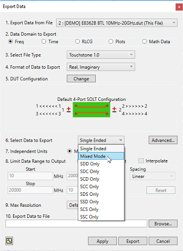 Click
the Browse button
to export the data to a file of your choice. Click
the Export button.
Import
the Diff/Com Port Reference Impedance Settings:
Select
File > Import...
> Single File.
The Import a Single File dialog is displayed.
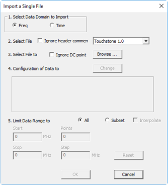 In
the Import a Single File dialog, click the Browse
button. Open
your data file. In
the Import a Single File dialog, click the OK
button. Select
the Frequency Domain (Balanced)
analysis view then click the OK
button.
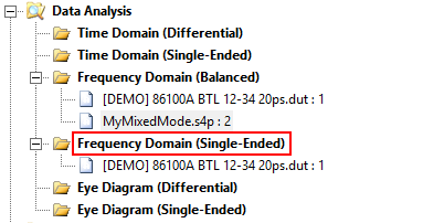
- Computing Single-Ended
Parameters:
At this point, the mixed
mode parameters have been imported in the Frequency
Domain (Balanced)
analysis view but the single-ended parameters have not been
computed based on the mixed mode settings. The following shows
the process for computing the single-ended parameters. For
purposes of this example, the mixed mode file is called MyMixedMode.s4p.
Select
Frequency Domain (Single-Ended)
analysis view.
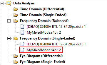
 The
MyMixedMode.s4p file
should be displayed:
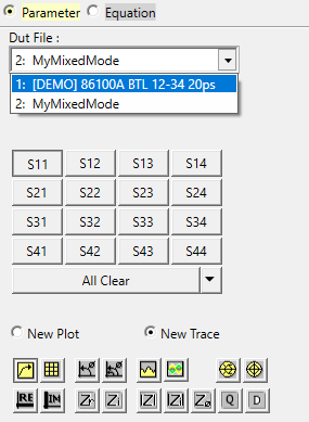
 In
the Parameter Format Selection,
click the ALL button
to display the single-ended plots. PLTS has now computed the
single-ended parameters based on the mixed mode parameters.
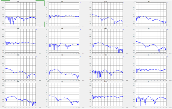 In
the Parameter Format Selection,
use the Dut File drop
down menu to select the original file.
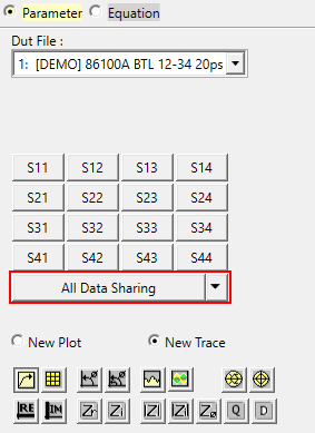
 Click
on the All Data Sharing
button to overlay the original single-ended plots onto the
MyMixedMode.s4p plots.
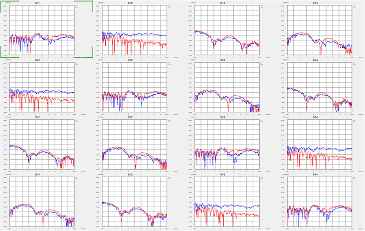
 Verify
that the plots in the MyMixedMode.s4p
file (blue) are different from the original plots (red).
Apply
Applies the adjustments to the active plot window. The data
displayed on the views will then be updated.
Close
Closes the dialog box.
Click File,
then Save to save the
adjustments to the *.DUT file. When the *.DUT file is loaded again,
the appropriate status bar indicators on the status bar will be
highlighted, and the dialog box will open with the list boxes
and reverse orientation check boxes initialized appropriately.
The De-embedding
indicator on status bar shows when the listed ports have de-embedded
data.
The Port
Rotation indicator on status bar is shows that at least
one port has been rotated.

|