Requires Advanced Calibration (5xP) PLTS license.
This wizard helps you design and verify 2-port TRL Cal Kit standards.
Note: This wizard is NOT used to design Differential (Balanced) TRL Cal Kits.
Click Calibration, then Design TRL Cal Wizard
The following wizard pages are presented in order:
Welcome dialog box |
To save your progress, click File, then Save on any TRL Wizard page. To continue your work at a later time, click File, then Open, and select your *.wzd file. Cal Kit definitions are stored at the following steps:
S2P files that contain TRL Standard measurements can be stored at Step 4 and Step 7. |
Design Cal Kit dialog box |
This page helps you to design the TRL standards that you will fabricate. Enter design information at the top of the page and press Calculate. PLTS recommends the physical lengths of each standard to fabricate and the Frequency Range and Delay of each. All standards are assumed to operate at 50 ohms. Design InputsStart and Stop Freq (MHz) Enter the frequency range over which the TRL Cal Kit will be used. Use Load Check if a Load standard will be fabricated. Load Max. Freq (MHz) Enter the frequency range over which you would like the load standard to be used. Reflect Type Select the type of reflection standard to be used (Short or Open). Freq Ratio (2-10) The ratio for each of the Line standards can be no less than 20° and no more than 160°. Multiple bands are required to cover the entire frequency range. For example: 160° / 20° = 8 and 150° / 30° = 5. Although the allowed ratios are 2 through10, ratios higher than 8 may result in degraded accuracy of the line standards. Effective Dk (dielectric constant) Enter the dielectric constant of the medium of the standards. Reference Length (1/2 Thru) Enter 1/2 of the length (in mm or inches) of a reference Thru. This would be the length of a Thru standard that is exactly the length of a THRU that extends from launch to launch. Calibration Standards DefinitionsWhen Calculate is pressed, the displayed values are updated to show the Standard, Frequency Range, Delay (in picoseconds), and the physical length of each standard. Update Cal Kit DefinitionsCal Kit Name Type a name for your new Cal Kit as it will appear in the PNA. Cal Kit Description Type a description for your new Cal Kit as it will appear in the PNA. Connector Type Enter the type of connector that is used on your new Cal Kit. Update Cal Kit Resets the Cal Kit definitions to designed values. Do this if the definitions were modified in Step 5 and Step 6 and you want to revert to the designed values. Use Step 10 to download the updated Cal Kit to the PNA. Save your progress in the wizardClick File, then Save. To continue your work after fabricating the standards, click File, then Open, and select your *.wzd file. |
3. Coaxial Calibration dialog box |
After the TRL standards have been fabricated, this step calibrates the PNA before measuring the standards. 1. Measurement SetupClick Modify to change the stimulus parameters for measurement of the TRL standards. Launches the Setup Hardware Dialog. 2. Cal Kit SelectionClick Modify to launch the Calibration Settings dialog. 3. Perform CalibrationEnter a name for the Cal Set that will result from this calibration. Click Calibrate to begin the PLTS Calibration Wizard.
Load PNA Cal Set. Instead of performing a Coaxial Cal, select a Cal Set on the PNA. |
Measure Cal Standards dialog box |
After the PNA is calibrated, existing files can be opened or the standards can be measured, and then analyzed in the following steps.
* Or *
Click Next> when all standards have been opened or measured to continue with the Verify Frequency Range page. |
Connect DUT dialog box |
This dialog allows you to test the connection of the DUT. When the connection is made, click OK to measure the DUT, store the results in the specified file, and return to the Measure Cal Standards page. Reflection, Transmission, Customize Check the boxes to list the parameters that are available for testing to the specified criteria. Click each parameter (in the highlighted area above) to select for testing. The BOLD parameters are selected. Pass/Fail indicator (Green box in red ring above)
Criteria Click to launch the Continuity Check Criteria dialog. Trigger Checking
Click OK when the DUT is connected to your satisfaction.
|
Continuity Check Criteria dialog box |
This dialog sets the Pass/Fail criteria for the Continuity Check. Select Choose an existing criteria. If only 'default' exists, click New to create new criteria settings. New Click to launch the Input New Name dialog. Type a name for the new criteria settings. The name of the settings in the above image is "Reflection". Delete Removes the selected Criteria settings. Rename Allows you to rename the selected Criteria through the Input New Name dialog. Save Saves the current settings to the selected Criteria. OK Close the dialog. |
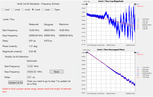
Verify Frequency Range dialog box |
Use this page to analyze the results of the measured TRL standards in the Frequency domain. Select a standard to view. Things to check:
Load StandardIn TRL calibration, a load standard is often utilized to cover the low frequency band. Specify the maximum acceptable return loss as the “Maximum Return Loss”. This means the load return loss must be lower than this value within its designed frequency range. The frequency corresponding to the “Maximum Return Loss” is defined as the load stop frequency. The load standard is required to have a low return loss (approx -50 dB). The return loss becomes worse at higher frequencies. Reflect StandardsThe phase response of the Reflect standard is compared with the Thru and the phase difference is used to calculate the delay. Verify Cal Kit Standards Select a TRL standard to analyze. Data is presented in the middle of the dialog. (Line / Thru).Measured - Designed - Maximum
Modify Cal Kit DefinitionsThe measured values are optimized values. Use this values or enter new Start and Stop frequencies, and Delay values, for the Cal Kit. Reset Clears the values that are entered. Update Cal Kit Saves the new displayed values to the *.wzd file on your PC.
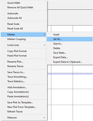
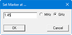
The Set Marker At... text box allows marker frequency to be entered manually.
|
Analyze Launch dialog box |
The data that is presented here is the same measurement data as the previous page, but in Time domain. Use this dialog to analyze the quality of the launches used in your fixture. In TRL calibration, the line impedance is often used as the reference impedance. Move the markers to specify a range to calculate the impedance variations, showing as a peak or a dip possibly. That is a measure of the launch repeatability. For the lines, you can select a line and specify the range for the line. Press Re-calculate to view the new Nominal Impedance values. Note: If any of the line lengths is less than 0.5 ns, the range is automatically set to 0.5 ns for all traces. Update Cal Kit Saves the new displayed values to the *.wzd file on your PC.
|
7. Current Cal Kit Definitions dialog box |
This page enables you to view the current cal kit parameters. You can also download the updated cal kit definitions to the PNA. |
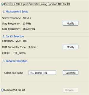
8. TRL Calibration dialog box |
Perform a TRL Calibration using the new standards to verify the performance of the Cal Kit. Click Modify to change the start frequency, stop frequency, or cal kit. Type a filename for the Cal Set when the calibration is complete. Then click Calibrate to perform the TRL calibration. Load PNA Cal Set. Instead of performing a new TRL Cal, select a Cal Set on the PNA. |
9. Re-Measure Cal Standards dialog box |
After the PNA has been calibrated using the new TRL calibration standards, existing files can be opened or the standards can be measured, and then analyzed in the following steps.
* Or *
Click Next> when all standards have been opened or measured to continue with the Analyze Cal Quality page. |
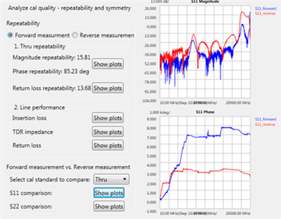
10. Analyze Cal Quality dialog box |
Allows you to view the measurements of the new TRL standards that were just used to perform the TRL calibration. RepeatabilitySelect Forward or Reverse measurement for the Thru and Line standards.
Note: It is important to realize that any variation from 'perfect' responses within the specified frequency range should be attributed to system repeatability, either in the standards or in the PLTS system. |