The following configurations can be used on the N522xA models for use with the IMD Apps (Swept IMD, IMDx, IM Spectrum, and IMx Spectrum).
These are NOT the only supported configurations, but are intended to be used as examples. However, base N522xA models (without front-panel jumpers) are NOT supported with the IMD Apps.
N522xA Specs - Block diagrams appear in the last pages.


External Source - see list of supported sources.
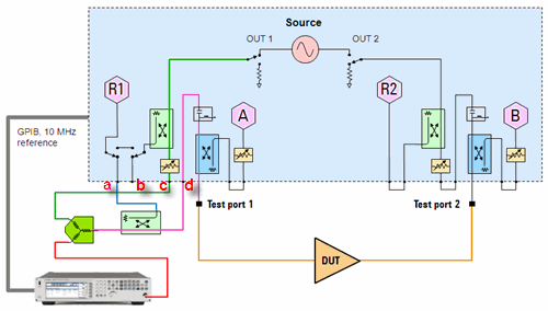
Combiner - Used to combine f1 (from internal source) and f2 (from external source).
Coupler - Used to route input tones to R1 receiver.
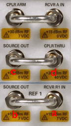
Cables - Used to make connections as shown in image.
The R1 reference switch MUST be set to "External". Press Channel then Hardware Setup then Test Set.
R1 receiver is used to measure both the f1 and f2 tones. R1 is inferred by the PNA when you select Port 1 as the DUT input on the IMD Setup dialog Power tab.
Connection at 'd' above is to measure DUT input reflections at receiver A.
Remove the front-panel jumpers with labels in above image.
Configure the setup as shown in above image.
In the External Source Configuration dialog, configure the external source.
In the IMD Setup dialog; Configuration tab, select the external source as f2 tone.
Port 3 coupler is used to combine f1 and f2.
Port 4 coupler is used as a splitter to route the tones to the R1 receiver.
You can also use external components for one or both of these functions for less loss or better power-handling capability.
This configuration can also be used for 4-port PNA-X models with no internal combiner.
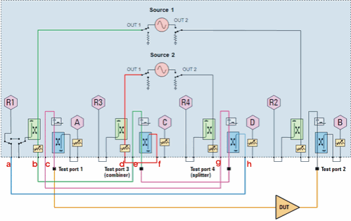
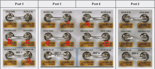
Cables - Used to make connections as shown in image.
R1 receiver must measure both the f1 and f2 tone. R1 is inferred by the PNA when you select Port 1 as the DUT input on the IMD Setup dialog Power tab.
Connection at 'c' above is to measure DUT input reflections at receiver A.
Remove the front-panel jumpers that have labels in above image. Not all front-panel connectors will be cabled when finished.
Configure the setup as shown in above image. Be sure to make connections to ALL four PNA test ports as shown in about image.
This configuration can also be used for 4-port PNA-X models with no internal combiner.
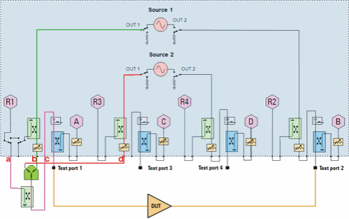
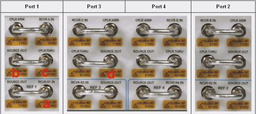
Combiner - Used to combine f1 and f2.
Coupler - Used to route input tones to R1 receiver.
Cables - Used to make connections as shown in image.
R1 receiver is used to measure both the f1 and f2 tones. R1 is inferred by the PNA when you select Port 1 as the DUT input on the IMD Setup dialog Power tab.
Connection at 'c' above is to measure DUT input reflections at receiver A.
Remove the front-panel jumpers with labels in above image.
Configure the setup as shown in above image.
Last modified:
|
1-May-2012 |
Added reference sw note |
|
4-May-2011 |
New topic |