This topic describes the basic configuration needed to connect a waveguide transmission reflection frequency extender directly to a PNA-X (without a N526x test set). This configuration will allow you to create an integrated 2-port banded waveguide S-Parameter measurement solution. In particular, it will focus on the options and configurations of the PNA-X as well as the settings required to make a complete measurement.
mmWave Configuration with a N526x Test Set
4-port PNA-X, or 2-port / 2-source PNA-X
Option 080 FOM. Learn more about FOM.
Firmware A.09.00 or greater
mmWave Modules
DC Power Supply for mmWave Modules
mmWave Cal Kit
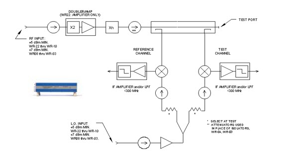
The frequency extenders being used should have the following basic architecture. This is an example of the OML modules, although other frequency extenders maybe used.
The key parameters to be aware of are:
Ensure that the PNA-X being used has sufficient drive power for the RF and LO signals. Since most frequency extenders typically operate in a saturated mode the PNA-X has sufficient RF port power to drive the OML, VDI, and Farran frequency extenders.
The IF output of the frequency extenders to the receiver input is less than the compression level of the PNA-X.
This configuration is limited to S-Parameters only.
Log Sweep is not allowed.
The following list of components applies to the example shown above:
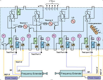
Connect the frequency extenders to the PNA as shown below:
This shows how one mmWave module is configured. When used with a 2-port PNA-X, the internal second source is used instead of port 3.
This same principal is used to configure the second mmWave module using ports 2 and 4.
Legend
Remove the jumper cables, then connect to the Receiver IN connectors.
|
Color |
PNA to 1st Module (PNA to 2nd Module) |
mmWave Module |
|
Orange |
Rcvr Ref 1 IN (Rcvr Ref 2 IN) |
Ref IF Out |
|
Blue |
Rcvr A IN (Rcvr B IN) |
Test IF Out |
|
Red |
Port 1 (Port 2) |
RF In |
|
Green |
Port 3 (Port 4) |
LO In |
Note: A macro is available that makes the following PNA settings automatically. Learn more.
In Power and Attenuators dialog:
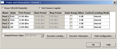
Set the Port 3 and Port 4 power to ON. (This allows LO power to always be ON).
Adjust the port power to adequately drive the mmWave module (12 dBm is this example).
Clear the Port Powers Coupled checkbox if the LO and RF power requirements are different.
In Path Configuration dialog, Set Port 1 Ref Switch to External. This is NOT necessary for rear-panel connections and on a second mmWave module connected to ports 2 and 4.
In FOM dialog:
Note: The following procedure shows mmWave frequencies from 75 GHz to 110 GHz.
To make the following Multiplier, Divisor, and Frequency settings, click in the Settings field for the corresponding Source or Receiver, then click Edit.
4. In Calibration Preferences dialog: To calibrate at the mmWave frequencies check the Use FOM Primary Frequency.
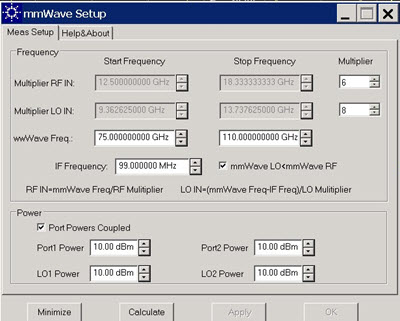
Using the macro will eliminate all of the steps involved in setting up the power and the attenuators as well as the Frequency settings. Download the macro from the following URL http://na.tm.agilent.com/pna/apps/mmwave_setup.msi .
Load the macro and enter the values for setting up the measurement.
Last Modified:
|
5-Feb-2015 |
Several changes from SS |
|
27-Aug-2013 |
Minor modification |
|
22-May-2013 |
Added Log Sweep limitation |
|
4-Sep-2009 |
MX New topic |