How to access Path Configurator
Using hardkey [softkey] buttons:
Using Menus:
-
Press trace/chan
-
then [Channel]
-
then [Hardware Setup]
-
then [Path Config...]
-
Click Trace/Chan
-
then Channel
-
then Hardware Setup
-
then Path Config...
Allows you to configure hardware components that are available with selected PNA-X options.
N522xA and N523x models do NOT have the RF Path Configurator.
How to access Path Configurator |
|
|
Using hardkey [softkey] buttons: |
Using Menus: |
|
|
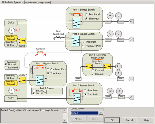
The following image shows configuration with PNA-X Opt 423 (4-port, internal 2nd source, combiner, and mechanical switches). Your PNA-X may not include these options.
PNA-X specs for block diagrams
Internal Second Source limitations
PNA Configurations and Options

|
See Noise Figure tab of the Path Configuration. Note: With selected PNA-X options, pulse modulation is available ONLY on OUT1 of Src 1 and Src 2. See block diagram. Different paths can be configured for each channel. ConfigurationSelect, store, and delete factory configurations or user-defined configurations. Configurations are stored on the PNA hard drive. Any configuration can be saved, and later recalled, from this dialog. Click Store, type a configuration name, then click OK. Text area Displays text describing the physical connections required to complete the configuration. The text for factory configurations can NOT be edited. Text is saved as part of the configuration. Cancel Closes the dialog and returns the configuration settings to the state they were in when the dialog was opened. Cancel does NOT undo Store and Delete actions that were performed while the dialog was open. Notes
Factory ConfigurationsNote: Recalling a stored configuration will over-write MANY RF and IF path configuration settings. Make your measurement settings AFTER recalling a stored configuration, NOT before. Port 1 2-tone Routes Source 2 through the internal combiner to create a two-tone signal out port 1. The standard jumper configuration is used. This is the configuration that is used to make IMD measurements. Src 2 Out Port 2 (Option 423 ONLY) Routes Source 2 (OUT1) to port 2 using an external cable attached to the rear-panel J8 to J1. This allows source power at port 1 AND port 2 simultaneously. Source power is NOT available at port 3. Learn more about Internal Second Source capability. 2 port Dual Source (Option 224 ONLY) Routes Source 2 (OUT1) to port 2 using an external cable attached to the rear-panel J8 to J1. This allows source power at port 1 AND port 2 simultaneously. This also allows pulsed measurements to be performed on both ports 1 and 2. Hot S-parameters The rear panel jumpers must be manually reconfigured to allow the source 2 signal to be routed through the thru path of the internal combiner. Source 2 is used to drive the AUT into compression, so the highest possible output power is required. Source 1, routed through the coupled path of the combiner, is used for S-parameter measurements, so a small signal is sufficient. These two signals are combined but the frequencies are usually offset. See Also |