External Millimeter-Wave Module Configuration
This feature, when used with the N526xA test sets and external mmWave
Modules, extends the frequency coverage of your PNA. The N5251A
broadband system is also configured using the Millimeter
Module Configuration dialog.
In this topic:
See Also
Other
IF Access Topics
Note: In the PNA
user interface and in this help file, the N526xA Millimeter Head Controller
is referred to as a test set.
The test head modules are referred to as mmWave
modules.
CAUTION: Turn OFF
test set power before connecting or disconnecting the DC cable to the
mmWave modules.
Features
The following Applications
are supported:
The following configurations are supported:
PNA-X or N522xA with options Opt
020 works with N5260A, N5261A, and N5262A Test Sets.
When using the N5262A test set, a 2-port PNA-X or
N522xA requires Opt
551.
Broadband - single
sweep from 10 MHz to 110 GHz.
Banded - frequency
coverage divided into bands.
Limitations
Power Settings
When using mmWave modules with an N5260A test set, the PNA can
NOT control the power level into your DUT. Your mmWave modules may
have a variable attenuator on them. When
used with an N5261A or N5262A, after performing a Source Power Cal,
then the PNA power settings may be used to control the power into
the DUT. See Leveled
Power Capabilities.
To protect your mmWave modules from damage, the settings
on the Millimeter Module Configuration dialog can ONLY be changed
manually. They can NOT be reset or changed by performing a Preset,
by recalling an Instrument State, or from a remote program.
ONLY the Applications
listed above are supported.
Broadband and
Banded mmWave Measurements
Broadband refers to mmWave configurations with a frequency range of
10 MHz to 110 GHz. This configuration spans the entire frequency range
in a single sweep.
Banded refers to any configuration that is not a broadband configuration
and is waveguide based. Frequency extenders cover frequency ranges from
50 GHz to 1.1 THz. The supported solutions can be configured for different
frequency bands with or without a test set controller depending on the
measurements required and the frequency extenders being used.
The following table shows the waveguide designation equivalents.
| MIL-DTL-85/3C |
IEEE Std 1785.1 |
Frequency Range |
| WR-15 |
WM-3759 |
50
GHz to 75 GHz |
| WR-12 |
WM-3099 |
60
GHz to 90 GHz |
| WR-10 |
WM-2540 |
75
GHz to 110 GHz |
| WR-08 |
WM-2032 |
90
GHz to 140 GHz |
| WR-06 |
WM-1651 |
110
GHz to 170 GHz |
| WR-05 |
WM-1295 |
140
GHz to 220 GHz |
| WR-04 |
WM-1092 |
170
GHz to 260 GHz |
| WR-03 |
WM-864 |
220
GHz to 330 GHz |
| WR-02 |
WM-570 |
330
GHz to 500 GHz |
| WR-1.5 |
WM-380 |
500
GHz to 750 GHz |
| WR-1.0 |
WM-250 |
750
GHz to 1.1 THz |
| Reference:
IEEE Standard for Rectangular Metallic Waveguides and their interfaces
for frequencies of 110 GHz and above - Part 1: Frequency Bands
and Waveguide Dimensions. |
PNA-X Notes
CAUTION:
Connect a 10 dB attenuator to the N5260A LO input from the LO
Output. Otherwise, damage will occur to the N5260A test set.
The PNA-X or N522xA rear panel IF
Inputs use 5 SMA connectors. Previous PNA models use BNC connectors.
Adapters may be required.
Beginning with A.09.00, Frequency Offset and SMC Measurements
are supported when using mmWave modules. Learn
more.
Beginning
with A.10.45, Spectrum Analyzer Measurements are supported when using
mmWave modules. Learn
more.
How to Configure
Millimeter-Wave Modules |
Using
front-panel
hardkey [softkey] buttons |
Using
Menus |
Press system then [Configure] then [Millimeter
Module] |
Click Utility then System then Configure then Millimeter
Module Config |
There are NO programming commands
to configure mmWave modules and test set. |
Millimeter
Module Configuration dialog box help |

|
Note: To
protect your mmWave modules from damage, settings on this dialog
can ONLY be changed manually or with a remote program. They
can NOT be reset or changed by performing a Preset, or by recalling
an Instrument State.
Available Configurations
Lists the Standard PNA configuration and other mmWave configurations
that you have created.
Click New
for first-time use. For the N5251A, select Broadband
10MHz - 110GHz. For banded, define a frequency band. Select Standard
PNA to exit mmWave module operation.
Selected Configuration
Shows the currently selected configuration. Edit this field
to change the configuration name. Type a unique name using only
alphanumeric characters and underscore.
New Click to create
a new Millimeter Module configuration. A name is automatically
selected. Edit the Selected Configuration field to change the
configuration name.
Remove
Deletes a Millimeter Module Configuration.
Test
Set Properties
Selected
Test Set Select a test set to use in the current
configuration. The firmware does NOT check to ensure that the
selected test set is connected.
Route PNA
RF to rear panel "SW SRC OUT" Available
ONLY on PNA-X with option
224 or 423 AND when using N5261A and N5262A test sets.
When checked, Port 1 source is switched
to J11 and Port 3 source is switched to J8 on the PNA
rear panel. Use this configuration to quickly switch
the RF Output back to the PNA front panel.
Mixer Mode
Check to allow mixer testing using SMC.
Learn more.
Enable
Test Set RF ALC Available for N5261A and N5262A ONLY.
When checked, power is automatically leveled at the mmWave
module RF input when using the standard cables and making non-pulsed
measurements. Clear this box to use non-standard cables or when
making pulse measurements. When cleared, the following fields
become available:
Max
Power Limit The maximum mmWave module RF input is
limited to this value when Test
Set RF ALC is OFF. When you exit this dialog box
using OK, set the power
out of the PNA using the Power
and Attenuator dialog.
Power
Offset Sets the loss of the cables. The mmWave module
RF input is adjusted by this
amount. Positive offset increases the power.
Power
Slope Helps compensate for cable and test fixture
power losses at increased frequency. The mmWave module RF input
power increases as the sweep frequency increases in dB/GHz. The
slope is defined relative to the mmWave module RF input frequency.
The slope starts at 0Hz and a positive slope will increase
the power level. Range is +/- 2
dB/GHz.
Note: Changing
any of the source controls after a calibration will cause the
source power cal to be turned off. A source power cal will need
to be performed again with the new settings.
Frequency
Settings
Multiplier
RF IN RF Frequency Range (displayed in grey fields)
multiplied by this value = test port frequency range.
Multiplier
LO IN LO Frequency Range (displayed in grey field)
multiplied by this value equals the test port frequency. The
IF frequency is:
'C'
Models = 8.333 MHz PNA-X
models = 7.605 MHz
Test Port
Frequency Set the Start and Stop frequencies of the
selected configuration at the test ports. This becomes the
displayed Start and Stop frequency of the PNA.
Important
Notes
To set Test Port Frequency, first
set the appropriate Multiplier
values that are specified in your mmWave module documentation. Ensure that the RF and LO Frequencies
(highlighted below) are within the frequency range
of the sources. The PNA offers no warning if they
are NOT.
|
Source
Click a button to launch the External
Devices dialog where you can select an internal or external
source to be used for the PNA LO source or PNA RF source.
Cancel Closes
dialog box without saving changes.
OK Saves the configuration
and the PNA is Preset
before making the appropriate settings. |
Mixer Mode
Mixer measurements can be made at mmWave frequencies using SMC.
(VMC measurements are NOT supported.)
Beginning with A.09.40, mixer measurements can be made with a 2-port
test set connected to a 4-port PNA-X. This configuration yields a 2-port
mmWave system. Learn
about 2-port system connections and limitations.
Before A.09.40, The Mixer Mode checkbox could be enabled ONLY when the
number of PNA test ports matched the number of ports on the mmWave test
set. This means that an N5261A (2 port test set) could ONLY be connected
to a 2-port PNA and an N5262A (4 -port test set) could ONLY be connected
to a 4-port PNA.
Procedure
Connect your DUT to the mmWave system as described
below.
Configure this dialog (Millimeter
Module Configuration). Check Mixer
Mode, then press OK.
This presets the PNA.
Create
an SMC measurement.
Make
mixer settings. As with standard SMC measurements, only two DUT
ports can be swept in frequency. The remaining DUT port must be a
fixed frequency. See
configuration used for harmonic mixers.
Increase
power for mmWave modules that are connected directly to a PNA
port or external source.
Calibrate using the SMC
Calibration Wizard with mmWave Power Control.
Hardware Connections
for Mixer mode
The following image shows the standard connections from a N5261A or
N5262A test set port to a mmWave module.

mmWave mixers usually require that two of the three mixer ports operate
at mmWave frequencies. When Mixer Mode
is checked on this dialog (Millimeter
Module Configuration), the following restrictions apply:
On a 2 port mmWave system, only port
1 of the test set can be used as a mmWave frequency port. Port
2 can NOT be used.
On a 4 port mmWave system, only ports
1 and 3 of the test set can be used as mmWave frequency ports.
Ports 2 and 4 can NOT be used.
The SMC
parameter being measured must be within the frequency range of
the PNA or within the frequency range of the banded mmWave module.
Frequencies in between these ranges are allowed by the SMC
mixer setup dialog, but the measurement results on the screen
are NOT accurate.
Connections with a 4-port mmWave system
Upconverters
DUT Input - Connect to PNA port 2 or port 4.
DUT LO - Connect mmWave module to test set Port 3.
DUT Output - Connect mmWave module to test set Port
1.
Downconverters
DUT Input - Connect mmWave module to test set Port
1.
DUT LO - Connect mmWave module to test set Port 3.
DUT Output - Connect to PNA port 2 or port 4.
Connections with a 2-port mmWave system
Although supported, testing mmWave mixers with a 2-port system can be
challenging for the following reasons:
Testing mmWave mixers requires that two of the three
DUT ports be at mmWave frequencies.
Only test set port 1 is capable of adequately driving
a mmWave module when used as a receiver.
Therefore, the second DUT port that requires mmWave
frequencies must have the mmWave module connected directly to an external
source or a PNA second source.
When using the mmWave module as a source, only the
DC Bias and RF cable is necessary. The LO cable to the mmWave module
is NOT used. This is because the RF input frequencies are multiplied
in the mmWave module to provide the source frequencies. So a mmWave
module used as a source can use the RF cable to connect directly to
the PNA second source or an external source. About +5 dBm of RF power
is required to adequately drive the mmWave module.
Downconverters - requires two
mmWave modules as sources
DUT Input - Connect the
mmWave module to the test set port 1.
DUT LO - Connect the
RF cable of the mmWave module to an external source or the PNA (SRC2)
second source.
DUT Output - Connect to PNA port 2.
Upconverters - requires a mmWave
module as a source at the DUT
LO and a mmWave module as a receiver
at the DUT Output:
DUT Input - Connect to
PNA port 2.
DUT LO - Connect the
RF cable of the mmWave module to an external source or the PNA (SRC2)
second source.
DUT Output - Connect the mmWave module to the test
set port 1.
Measuring Harmonic Mixers
Harmonic mixers have a multiplier circuit in the LO port of the DUT.
Enter the multiplier value in the numerator of the X LO port in
the SMC
mixer setup dialog. This will provide the correct LO frequencies
out of the appropriate source.
Spectrum
Analyzer mmWave Measurements
Beginning with A.10.45.xx, spectrum
analyzer measurements can be made at mmWave frequencies using the Option
090 Spectrum
Analyzer application plus Option 093 or Option 094.
Broadband and banded mmWave measurements are supported. The test set configuration
is required for both.
Options 093 and 094 are mmWave
measurement options specific to the Spectrum Analyzer application. Broadband
measurements require Option 093 and measure from 10 MHz to ≤ 110 GHz.
Banded measurements require Option 094 and measure frequencies > 110
GHz.
Note: The IF
Response Adjustment must be performed each time a new configuration
is set up or if cables are changed.
The following procedure outlines
the steps required to set up a spectrum analyzer mmWave measurement.
Configure
the mmWave measurement using the Millimeter Module
Configuration dialog.
On the PNA
front panel, press Meas, then
[Measurement Class].
Select
Spectrum Analysis, then either:
A
Spectrum Analysis measurement
is displayed. Learn
about setting up a Spectrum Analyzer measurement.
Select
other mmWave supported measurement classes as needed.
mmWave Module Power Level Control
Beginning with A.09.40, the following TWO features are integrated into
Guided Cal:
The following table shows features that can be used to provide leveled
power to the input of your DUT for S-parameter and SMC measurements.
Feature |
Description |
Use
when... |
Use
for... |
Access
the feature... |
Receiver
leveling |
Provides
a sweep-to-sweep leveled power. |
Works
anytime. |
S-params
and SMC |
Before
or after Cal |
Use
Multiple Sensors |
Allows
several power sensors to be used to calibrate source power. |
You
require more than one power sensor to complete the source power
calibration of the measurement frequency range. |
S-params
and SA |
During
Guided Power
Cal |
Power
Table |
Build
or use a file that contains data of mmWave module output power
vs frequency. |
A
power sensor is NOT available for calibration of the mmWave modules
being used. |
S-params |
During
Std Source Power Cal |
SMC
and SA |
During
Guided Power
Cal |
Calibrate
the source at multiple power levels |
Source
power is measured using the specified power meter/sensor or PNA
receiver to construct a 2D power table. |
A
component is used in the source path which does not have NOT linear
gain or loss over frequency. |
S-params |
During
Std Source Power Cal |
S-parameter measurements
If you have one or more power sensors that spans the frequency range
of your measurement, then use the following process.
Otherwise, perform a standard Source Power Cal. Learn
how.
Using one or more power sensors
Check ALC
Enabled (if available) on the Millimeter
Module Configuration dialog.
With an S-parameter measurement active, press Cal, then Start
Cal, then Calibration Wizard,
then SmartCal.
On the following Select
Ports dialog, check Calibrate
source and receiver power, then click Next.
Important:
In the following dialog, check Use
Multiple Sensors, even if using only one sensor.
Learn
about this dialog.
Complete the Guided Cal process.
Note:
During the 'Connect a power sensor to port n'...step, the following error
message may be displayed:
The
default power level of 11 dBm is unachievable after calibration. Lower
the power before starting calibration.
This means that a high amount of loss was
measured in the path, and 11 dBm at the test ports will not be possible.
Cancel
the calibration and lower the source power level using the Power
and Attenuators dialog.
Perform a standard Source Power Cal
- S-parameter measurements
When one or more power sensors that spans the frequency range of your
S-parameter measurement are NOT available, then use the following process.
Note: Perform an
S-parameter calibration AFTER performing the following Source Power Cal.
Check ALC Enabled
(if available) on the Millimeter
Module Configuration dialog.
Press Cal,
then Power Cal then Source Cal then Options
to launch the following dialog:
See
the help topic for this dialog
If one does not already exist, create a power table
to be used to calibrate the PNA receiver. Learn
how.
Check Use a power
table and the PNA reference receiver.
Click Power Table,
then navigate to the *.prn file.
Click OK.
Check Calibrate the
source at multiple power levels.
Click Power Levels,
then enter the Max power, Min power, and Step Size at which source
power should be corrected. Be sure that the source power for your
measurement is within these power levels. Otherwise, source power
will NOT be accurate. Learn
more about this feature.
Check Calibrate the
PNA reference receiver, then click OK.
On the Source Power Cal dialog, click Take
a sweep. The output of the test set is set to Max power
and a sweep is performed to calibrate the reference receiver.
Power is dropped for several subsequent sweeps. The
calibrated reference receiver is used to fully characterize the source
power.
The entire correction table can be saved along with
the instrument state in a *.csa file. Learn
how.
Power out of the input module should be flat and accurate.
SMC Cal
Use the following calibration process to achieve accurate, leveled power
at the mmWave test ports.
With a configured SMC measurement active, press Cal, the Start
Cal, then Calibration Wizard.
At the SMC Calibration
Setup dialog, when a Thru standard is NOT available, check Independent power cals for input and output
ports (no thru).
On the Select Ports
dialog, check Calibrate source and
receiver power, then click Next.
At the following Power Cal settings dialog:
Learn
about this dialog
When you have ONE power
sensor that spans the frequency range of your SMC measurement,
then click Power Meter Settings
to configure the power sensor. There are currently NO provisions
for using multiple power sensors with SMC Calibration.
Otherwise, use the
following Power Table process.
If one does not
already exist, create a power table to be used to calibrate
the PNA receiver. Learn how.
Check Use
Power Table.
Click Power
Table, then navigate to the *.prn file. The selected
*.prn file is annotated to the dialog.
Click OK.
If you checked Independent
power cals for input and output ports (no thru), you will ALSO
be prompted to select a power table for Port 2.
Complete the Guided
SMC Cal process.
Power Table
Note: This is NOT
the same table that is used for the Calibrate
the source at multiple power levels feature.
A power table is a text file with data that describes the output power
of the module as a function of frequency. This is valid when the
mmWave module is driven at high levels (+11 dBm). This file may
have been created for you by a third party or shipped with your mmWave
Module. If not, you can create this *.prn file from the manufacturer's
specification for the mmWave module.
This file can be created manually, using a text file program such as
Notepad. Copy the header information, and create the file with two
columns, one for frequency and one for output power.
Example .prn file
Note: With Rev.
09.31, the first line of the *.prn file must have the Input power at which
these measurements were made. Otherwise, an error message appears with
the default value that will be assumed. See above image for format.
Using
Cal All Wizard for Supported mmWave Measurement Classes
Beginning with A.10.45.xx, the
Cal All Wizard can
be used to calibrate broadband and banded configurations.
A power table can be used instead
of multiple power sensors to cover a wide frequency range. In addition,
a power table can be used when the measurement frequency exceeds the frequency
range of the power sensor (typically > 110 GHz). Refer to Power Table for information
on how to create a power table.
The
power table file name must be powertable1.prn,
where "1" corresponds to the port number. This file must be
stored in the following directory on the PNA:
C:\ProgramData\Keysight\Network
Analyzer\Configurations\<configuration name>\
where configuration name
is a directory name that is also the name of the currently selected configuration
in the Millimeter Module Configuration
dialog.
Once the power table has been
created and saved to the directory shown above, it will be listed in the
Sensor
drop down menu in the Power
Cal Settings dialog where it may be selected instead
of a power sensor.
Check
ALC
Enabled (if available) on the Millimeter
Module Configuration dialog.
Ensure
that the measurement classes to calibrate are active.
Press
Cal, then Start
Cal then Source Cal
then Cal All Wizard to launch
the following dialog showing the active measurement classes:
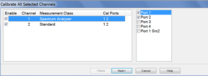
Select the
ports, click Next, then confirm
or change the calibration properties in the Measurement
Class Cal Properties dialog.
Click Next. to access the Calibration
Attenuator Settings dialog.
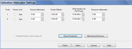
In the Calibration
Attenuator Settings dialog, perform the following:
Set the
attenuator settings. Learn
more.
Click on
the Noise Reduction button
to improve measurement accuracy. Learn
more.
Click on
the Mechanical Devices
button to view all switches and attenuators in the PNA. Learn
more.
Click Next, then select the DUT connectors
and calibration kits in the Select
DUT Connectors and Cal Kits dialog.
.Click Next to access the Power
Cal Settings dialog.
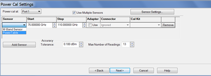
In the Power Cal Settings dialog, perform
the following:
Check Use
Multiple Sensors if more than one power sensor is needed
to cover the frequency range then select a sensor from the Sensor down menu.
Otherwise, check Use Multiple Sensors then select
the power table from the Sensor
drop down menu. Learn how to create a power table.
Learn
more about Accuracy
Tolerance and Max
Number of Readings.
Click
Next and follow the calibration
process until completed.