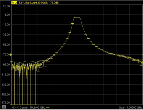
All VNA measurements have some level of uncertainty. The Keysight Uncertainty Calculator has always provided a method to calculate the uncertainty of your measurement based on measurement settings, connectors, and a specified Cal Kit. Now, with Option 015, you can display the measurement uncertainty dynamically ('real-time') on the same screen as the measurement trace and get more reliable uncertainty estimates.
The following three sources of uncertainty are characterized and accounted with Dynamic Uncertainty for S-Parameters:
Highlighted steps are required ONLY for noise and repeatability characterizations. They are NOT required if already completed prior to calibration.
Setup the instrument for characterization.
In Uncertainty Manager, assign Cal Kits, ports, and cables for measurement.
Perform noise characterization.
Complete a standard calibration of the system.
Perform repeatability characterization.
Setup the VNA for the measurement.
Perform an uncertainty calibration using an Uncertainty Cal Kit. Learn how.
Set Uncertainty Trace Properties to control what and how uncertainties are displayed. Learn how.
Note: When recalling a Uncertainty Cal Set, it is also necessary to turn Correction ON.

Filter S21 measurement with uncertainty bars.
When Programming Dynamic Uncertainty
Uncertainty Manager is used to perform Noise and Cable Repeatability characterizations, to edit Uncertainty Cal Kits, and make settings that are used during a subsequent uncertainty calibration. Once completed, the characterizations and settings can be saved to a workspace file for future calibrations.
Uncertainty Manager is a separate application that runs at the same time as the PNA application. It is closed ONLY when the PNA application is closed.
Important: To return to the PNA from Uncertainty Manager, click File, then Switch to VNA.
|
Using front-panel |
Using Menus |
|
|
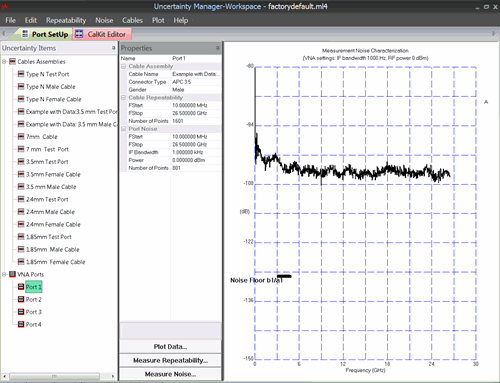
Most Uncertainty Manager settings can be made both from the Menu and by right-clicking an item.
The Uncertainty Manager Workspace contains all of the settings and characterizations that are used in an Uncertainty Calibration.
When an uncertainty calibration is performed, the workspace is automatically saved. This file is automatically reloaded when Uncertainty Manager is started.
The Noise characterization measures the PNA source and receiver noise for a pair of test ports.
When included in uncertainty analysis, the Noise Characterization is interpolated over frequency, but NOT extrapolated. Therefore, the characterization should be performed over the entire frequency span of the VNA with a point spacing of about 1600 points for the entire span. Avoid very dense point spacing as this slows the characterization and puts a burden on PNA memory.
The IFBW for the characterization should be within 10x of the IFBW of the uncertainty calibration. For example, a characterization performed at 10 kHz will allow the IFBW for the uncertainty calibration to be between 1 kHz to 100 kHz.
The power level is generally tolerant of variation, so performing the characterization within +/- 10 dB of the power level of the uncertainty calibration is acceptable.
The averaging factor of the characterization should be within a ratio of 1:100 of the uncertainty calibration. For example: an averaging factor of 100 for the characterization would allow an averaging factor of between 1 and 1000 for the uncertainty calibration.
It is NOT necessary to perform or recall a VNA calibration before performing a noise characterization.
Start the noise characterization by doing either of the following:
If the current VNA settings (frequencies, RF power, IF bandwidth) are NOT the same as that with which the current noise data was measured, then the following dialog appears:
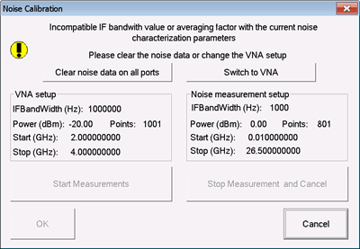
Select one of the following:
Click (Start) Measure. The VNA port noise characterization is performed using a 2-step measurement process involving two ports at the same time:
The noise floor is characterized with a LOAD (or low-reflective device) connected to each test port. If test cables will be used in your uncertainty measurement, connect them for the noise characterization to get a better noise estimate, especially when the cables are lossy.
Trace noise is characterized with a SHORT (or high-reflective device) connected to each test port.
Press OK when finished.
The noise data can now be saved and later recalled for use with uncertainty measurements.
Uncertainty Manager comes preloaded with a database of uncharacterized cables. In addition, there are also some 'Example' cables which include repeatability characterization data. However, you should perform your own repeatability characterization for cables which you intend to include in the uncertainty analysis.
It is likely that you will need to add new cables to the list. For example:
 next to the current cable name, then select a cable.
Select the cable to characterize.
If there is already repeatability data associated with the cable, right-click the cable, then click Clear Repeatability.
At the bottom of the Properties pane, click Measure Repeatability. The following dialog appears:
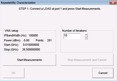
Choose Number of Iterations (20 is recommended). An Iteration is a measurement with each termination. A set of iterations are performed first with the LOAD (or low-reflective device), and then again with the SHORT (or high-reflective device). For 20 iterations, a total of 40 measurements are performed.
Connect the cable to the specified test port, connect the terminating LOAD, and click Start Measurements.
Between each measurement, either move the cable, or remove and reconnect the standard, or both (recommended). Do NOT remove and reconnect the cable from the VNA test port as this will impair the calibration. Use the same torque wrench as you use during ordinary calibrations and measurements.
Follow the prompts at the top of the dialog. When finished, press OK.
The repeatability data can now be saved and later recalled for use in an uncertainty calibration. The repeatability data can be used over any subset of the characterized frequency range. When used in an uncertainty calibration, measurement settings such as power and IFBW are NOT relevant.
From Uncertainty Manager, you can access the Uncertainty Cwwal Kit Editor by clicking the CalKit Editor tab. Also from the VNA Cal Kits dialog, click Uncertainty Cal Kits button.
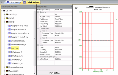
The Uncertainty Cal Kit Editor
To see Cal Kit uncertainty contributions in an Uncertainty calibration, the standards must include uncertainty data. This is best done with 'databased' standards. This means that the standard definitions include characterized data, not just polynomial values as in typical Keysight Cal Kits. Polynomial standards can include mechanical dimension uncertainties. Learn more.
As shown in the above image, three of the Keysight 8505x Cal Kits have already been 'databased' for use with Dynamic Uncertainty. In addition to being databased, the standards include uncertainty data.
All standards have properties as shown in the Properties pane above.
All standards have the General information shown, and Connector Type and Gender.
All standards have an icon preceding its Name in the Items list. This gives a hint as to the type of standard.
 - Signifies a databased standard. The characterization data is stored in the workspace file. See How to Characterize Uncertainty Standards.
 - Signifies an adapter. Adapters are NOT databased. They include only nominal 'delay'. This delay value can be edited if it is in a custom Cal Kit.
 - Signifies an OPEN. All other icons represent a specific type of polynomial-based standard.
To add a new connector, right-click on Connectors, then New Connector. "New_Connector" appears in the list of connectors. Edit the name in the Properties pane. It will now appear in the Connector Type selector for a standard.
You may need to create a custom Cal Kit for one or more of the following reasons:
Create a Cal Kit to contain new standards.
To be used in an Uncertainty calibration, the standards must include uncertainty data. This is best done with a 'databased' standard. This means that the standard definitions include characterized data, not just polynomial values.
Select Keysight Cal Kits have already been characterized with uncertainty data. If you own one of these Cal Kits, shown by name in the Cal Kit editor, there is nothing more required.
If you do NOT own one of these Cal Kits, you can characterize your own uncertainty standards.
Procedure
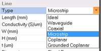
For Cal Kits that include polynomial standards to be used for PCB, on wafer, or coaxial applications, you can describe the mechanical dimensions and tolerances. From these, Uncertainty Manager will calculate the electrical uncertainties. An example of this type of standard is provided in the Uncertainty Manager Microstrip Example Cal Kit.
|
Calibration Options dialog box help |
|
|
To start this dialog, in Uncertainty Manager, click File, then Uncertainty Options.
Check each to include Noise, Cable Repeatability and Standard Definition in the uncertainty calibration. You can later decide to NOT include these in the measurements using the Trace Properties dialog. Max Uncertainty Pts - Because of limited PNA memory, uncertainty is computed for a maximum of 501 equally-spaced data points. When applied to a measurement, the data points within each step is assumed to have the same uncertainty. To save PNA memory, reduce this number.
Service Mode - When requested by Keysight service personnel, check this box before calibration to save uncertainty data for troubleshooting purposes. |
|
Important: BEFORE starting an uncertainty calibration, ensure that the current Uncertainty Manager workspace contains ALL of the settings that will be used for the uncertainty calibration. Here are the critical settings:
|
Start Cal Wizard, then select Guided Cal.
At the Select Ports for Guided Cal dialog, select the ports to be calibrated, then check Use Uncertainties, then Next >.
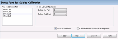
At the Select Cal Kit dialog:
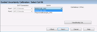
|
How to change Cal Types
2-port (Thru) Cals are selected by default based on the following (in order):
1-port Cals
Default CalsSelect your Cal Type preference for the current calibration.
|
Save the calibration and apply the resulting Cal Set with uncertainties as you would any Cal Set.
Important: Add a descriptive prefix to the Uncertainty Cal Set name such as "UNC<calset name>". This will help identify it as an Uncertainty Cal Set. This does not occur automatically.
You have performed Noise and Cable Repeatability (optional).
You have performed a calibration using an Uncertainty Cal Kit.
Now, you want to show the uncertainties on the displayed trace.
|
Start the Trace Uncertainty Properties dialog by doing either of the following: 1. Right-click on the PNA graticules (NOT the trace), then click Uncertainty Property. |
|
|
Using front-panel |
Using Menus |
|
|
|
Trace - Choose the displayed trace to which the settings on this dialog will be applied. Or check Apply to all traces to override this selection. Trace TypeONLY Ellipse is supported in Smith Chart or Polar display format. Normal - Display the trace without uncertainties. UMax – Display the trace as the uncertainty maximum (measured or memory data PLUS upper limit uncertainty values). UMin - Display the trace as the uncertainty minimum (measured or memory data MINUS lower limit uncertainty values). UBars – Display the uncertainties as “error bars” around the trace. Shade – Display the uncertainties as a shaded region around the trace. Ellipse – Display the uncertainties in ellipse form. Supported ONLY in Smith Chart or Polar display format. SettingsCoverage Factor - Sets the level of confidence used in computing the specified measurement uncertainties. The higher the coverage factor, the higher the confidence that the computed uncertainty region includes the "true" measured data of the DUT. To include Noise and Cable Repeatability uncertainties, the characterization must have already been performed. Learn how.
Apply to all traces - Check to apply the above settings to ALL traces. Clear to use the 'Trace' selector to choose traces to which settings will be applied. Add TraceA trace is added to the channel. Choose from the following:
Cancel - Closes the dialog just like clicking OK. All changes are applied. |
Once an Uncertainty Calibration has been performed and you are making measurements, you can then save Uncertainty data.
Before saving, an Uncertainty Calibration MUST be applied to the active measurement.
Click File, then Save Data As. (See the Save Data dialog).
Then choose from the following formats:
(*.u*p) S-parameter Uncertainty File - Very similar to *.SnP files except this format includes uncertainty data.
Sample header:
!Coverage factor: k=1
Freq(Hz), S1_1 mag (linear), S1_1 phase (deg), US1_1 mag (linear), US1_1 phase (deg)\
(*.sdatcv) METAS S-parameter Covariance File - Used by Swiss Federal Institute of Metrology software for save/recall of measurement uncertainties.
|
This dialog appears when any of the following conditions exist while attempting to save data to any of the Uncertainty data types:
Number of ports Select the number of ports for which data will be saved.
Arrow buttons Click to Add or Remove ports from or to the following columns: Available Ports All test set ports are listed. There may NOT be valid data available for all of these ports. Learn more. Chosen Ports When OK is clicked, uncertainty data is saved for these ports. OK Becomes available when the number of Chosen ports = the Number of ports to save. Click to save the uncertainty file. |
||