See Differences between the PNA-X and N522xA Models
See N523xA rear-panel.
Click image to learn more.
10 MHz Reference Input When a 10 MHz external reference signal is detected at this port, it will be used as the instrument frequency reference instead of the internal frequency reference.
10 MHz Reference Output This BNC(f) connector outputs a frequency reference signal for use by other test equipment.
See SCPI command that detects an external reference signal at this connector.
This USB hub contains two SuperSpeed USB ports to power your VNA peripherals. There is also one USB port below the LAN connector and four USB ports on the front panel.
Limitation: The total power consumption for all eight USB ports is limited to 4.0 amps. If this limit is exceeded, all USB ports are disabled until a device is removed and power consumption falls below the limit. When first connected, Keysight ECal modules 8509x and N4431 draw significantly more current than other modules. See Specifications.
See Important First-time USB connection note.
This 10/100BaseT Ethernet connection has a standard 8-pin configuration and auto selects between the two data rates.
The Mini DisplayPort is a miniature DisplayPort connector for connection to external displays.
The PNA-X can be a GPIB Controller and Talker/Listener. Learn more.
The PCIe X4 connector is a 4-lane slot for future enhancements.
These connectors are NOT available on the N522x and N5264A models.
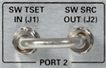
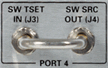
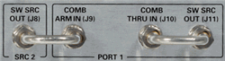
These connectors allow RF Path Configuration.
Ports 3 and 4 are not available on 2-port models.
N5247A - J8 thru J11 are moved to the front-panel.
|
|
|
|
|
The RF OUT connector is NOT available on the N5264A
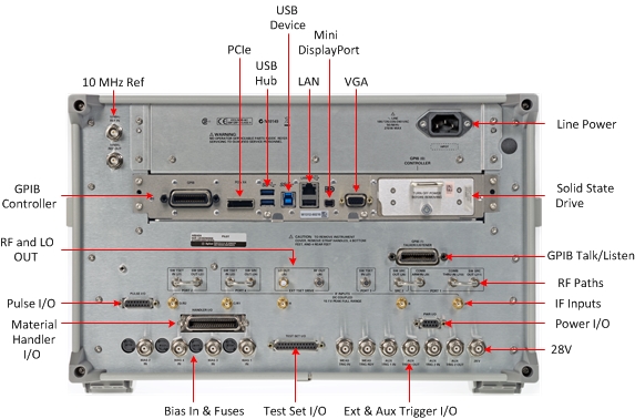
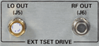
For the N5247A and N5227A:- Added RF2 OUT (J12) for 4-port 110 GHz single sweep PNA. Enables driving two mmWave modules simultaneously. Learn more.
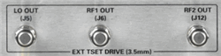
Caution: LO OUT has more power than previous PNA models.
Option 020 adds these connectors, which allow access to the PNA Receiver / IF paths.
![]()
These are labeled A, B, C/R1, D/R2, R.
For 2-port models, use A, B, R1, R2.
For 4-port models, use A, B, C, D, R.
See IF Path Configuration settings and block diagram.

Used to power a noise source for the Noise Figure App.
|
|
|
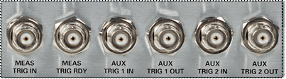
MEAS TRIG IN - When enabled, PNA is triggered by signals on this connector. Learn more. |
|
MEAS TRIG RDY When enabled, PNA outputs a 'READY' signal on this connector to other devices. Learn more. |
|
AUX TRIG 1&2 IN When enabled, PNA accepts signals on these connectors which indicates that the external devices is ready to be triggered. Learn more. |
|
AUX TRIG 1&2 OUT When enabled, PNA outputs signals on these connectors either before or after a measurement. Learn more. |

Connect your DC Power Supply to apply Bias to the PNA ports through these BNC connectors.
The bias fuses are rated for 0.5A. You are responsible to ensure that devices connected to the test port do NOT draw more current than 0.5A. This will occur, for example, if a calibration SHORT is connected to the test port with bias power ON. The fuse Keysight part number for the PNA-X is 2110-0824.
The PNA will meet all of its RF specifications with bias up to 200 ma. As the DC bias is increased, corrected source match and directivity will degrade at low RF frequencies.
See Determine Your PNA's CPU Version (Internet connection required)
See Service Guide to learn how to remove the SSD. (Internet connection required)
See Preventing PNA SSD Problems