Note: The Phase Noise Application applies ONLY to PNA/PNA-X instruments with serial prefix 6021 and above.
The Option S93031xB Phase Noise application measures the phase noise of a DUT's output signal within a specified offset frequency range.
In this topic:
Absolute Phase Noise measurements
AM noise measurement
Spur identification and removal
Automatic carrier search
Extensible to mm-Wave
Phase Noise Option S93031xB
2-Port or 4-Port PNA/PNA-X instruments with serial prefix 6201 and above (new Direct Digital Synthesizers)
Windows 10 operating system
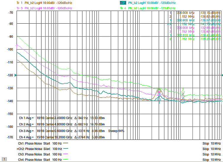
The noise floor for 2.4 GHz, 4.8 GHz, 9.6 GHz, and 19.2 GHz frequencies rises at an offset frequency of 300 kHz as shown in the following plot:

The following are typical hardware setups for measuring the phase noise of a device. The Option S93031xB Phase Noise application is installed on the PNA/PNA-X.
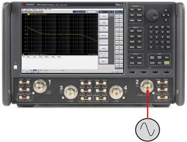
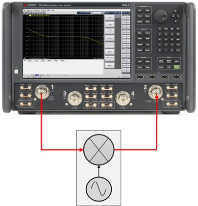
The Phase Noise application measures the power density of the noise sideband relative to the power of the carrier over a start/stop offset frequency. The offset frequency corresponds to the distance from the carrier frequency. The log-transformed phase noise is displayed in dBc/Hz.
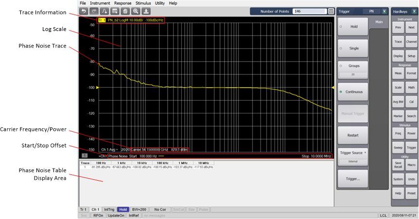
The bottom of the display area shows the carrier frequency, carrier power, and the Phase Noise start and stop offset frequencies. The x-axis is the offset frequency range displayed on a logarithmic scale to allow viewing the full offset range. Also displayed is the delta frequency indicator next to the Carrier Frequency. The delta frequency displays the frequency from the nominal carrier frequency. The actual carrier is not tuned exactly to the nominal carrier frequency. The delta indicator displays this frequency difference.

If the sweep time is greater than 2 seconds, a sweep indicator is displayed at the bottom of the display area to provide sweep time percentage complete:

Noise tables showing Spurious, Integrated Noise, and Spot Noise data can be displayed below the trace area.
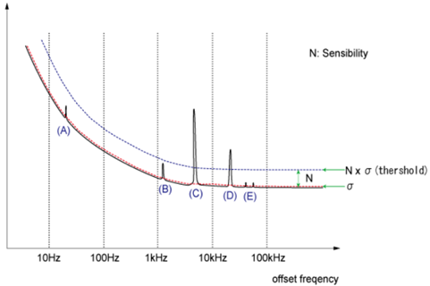
Spurs can be analyzed using Spurious Sensibility or by defining Threshold levels.
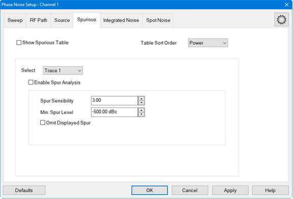
Spurious Sensibility = Sensibility Value x Standard Deviation (or sigma).
The Spurious Table can be displayed below the trace area of the display showing Trace and Spur number, Offset frequency, Power level, and Jitter.

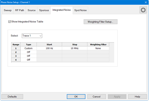
Integrated noise is the single sideband noise integrated over a measurement bandwidth from a start/stop offset frequency. Up to four offset frequency ranges can be defined.
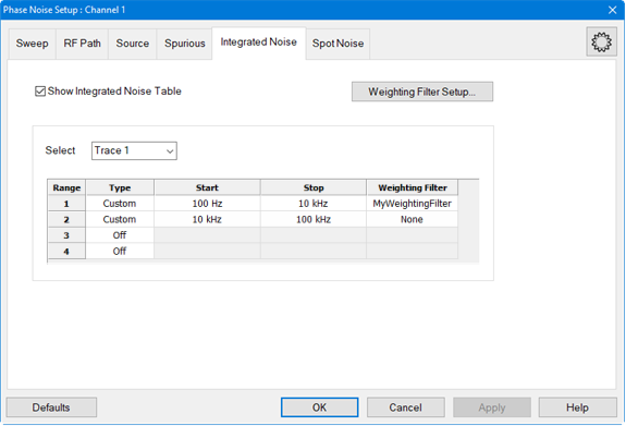
A weighting filter can defined and saved to a file for later use. The weighting filters compensate external effects that affect the phase noise in the specified frequency ranges. When the weighting filters are applied, the trace data are corrected by the filter characteristics before the calculation of integrated noise.
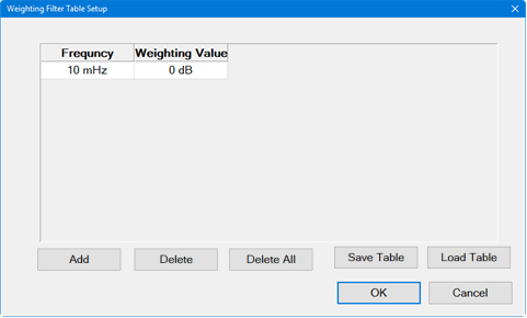
The Integrated Noise Table can be displayed below the trace area of the display showing trace number, start/stop offset, weighting filename (if used) integrated noise, phase modulation measured in degrees and radians, residual FM (Hz) or residual AM (%), and jitter.

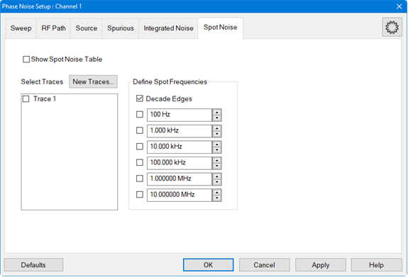
Spot Noise measurement are measurements made at specific frequencies. The measurements can be made at each decade, determined by the start/stop offset frequencies, up to six defined frequencies, or a combination of both decade and defined frequencies.
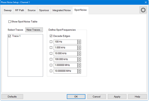
The Spot Noise Table can be displayed below the trace area of the display showing the specific measurement frequencies and the phase noise in dBc/Hz.

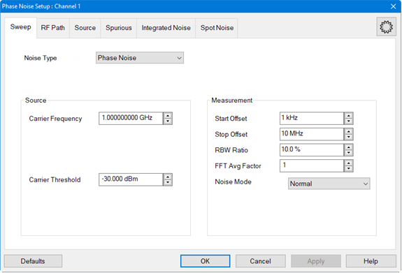
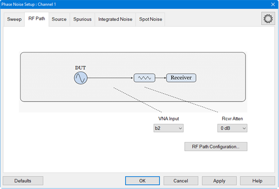
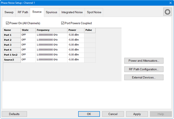
The GUI consists of setup dialogs accessed by clicking on their corresponding tabs. In this way, configurations can be set up quickly. See Configuring Phase Noise for information about these dialogs.
