1st Order PLL
The First Order PLL clock recovery method models the response of an ideal first-order hardware PLL.
You can specify the PLL's response in terms of either the JTF's 3 dB bandwidth or the OJTF's 3 dB bandwidth. JTF and OJTF 3 dB bandwidths are the same because it is first order.
![]()
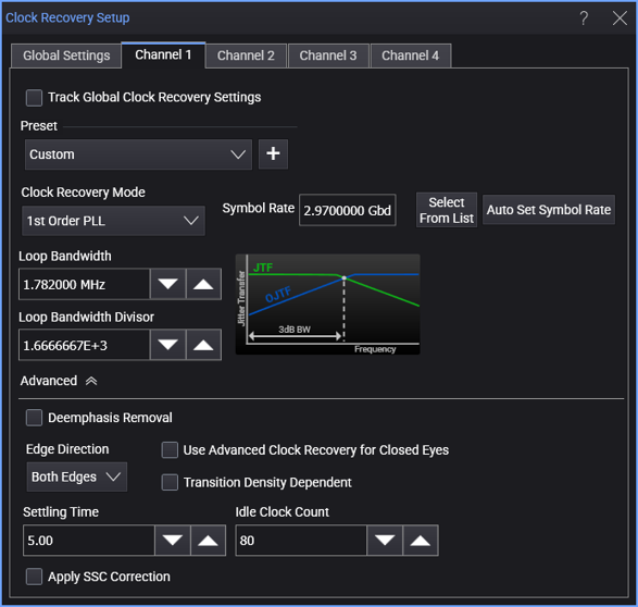
When the 1st Order PLL clock recovery mode is selected, the dialog box has these controls:
-
Symbol Rate — Enter the signal's expected baud rate.
The Select From List drop-down menu lets you select typical rates for standard communication interface technologies. The Auto Set Symbol Rate button runs a data rate measurement and populates the Symbol Rate field with the data rate measured on the input signal.
-
Clock Skew — For PAM type signals, this can be used to center the eye opening at the clock locations by shifting the clocks relative to the data.
-
Loop Bandwidth — You can specify the PLL's loop bandwidth either by entering it directly in the Loop Bandwidth field (also known as the -3 dB BW) or by entering the Loop Bandwidth Divisor value.
-
Loop Bandwidth Divisor — Enter a number that you divide the Symbol Rate by to get the loop bandwidth.