3rd Order PLL
The Third Order PLL clock recovery method models the response of an ideal Type III, third-order hardware PLL.
You can specify the PLL's response in terms of its Natural Frequency (ωn), Pole Frequency (ωp), and Damping Factor (ζ).
![]()
Note that the following equations use the angular frequency, ω (in radians/sec) which is equivalent to 2πf, where f is frequency (in Hertz).
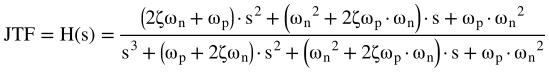
The Third Order PLL's Jitter Transfer Function looks like this:
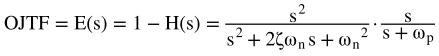
The Third Order PLL's Observed Jitter Transfer Function (or Error Function, hence, E(s)) looks like this:
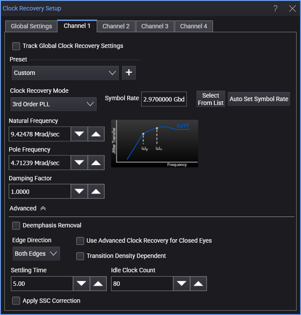
When the 3rd Order PLL clock recovery mode is selected, the dialog box has these controls:
-
Symbol Rate — Enter the signal's expected baud rate.
The Select From List drop-down menu lets you select typical rates for standard communication interface technologies. The Auto Set Symbol Rate button runs a data rate measurement and populates the Symbol Rate field with the data rate measured on the input signal.
-
Clock Skew — For PAM type signals, this can be used to center the eye opening at the clock locations by shifting the clocks relative to the data.
-
Natural Frequency — ωn in the previous equations.
-
Pole Frequency — ωp in the previous equations.
-
Damping Factor — ζ in the previous equations.