5th Order PLL
The Fifth Order PLL clock recovery method is the same as the PCIe 5/6 CXL Behavioral SRIS CC clock recovery methods except that it gives you control over the CDR (clock and data recovery) filter angular frequency parameters ω0, ω1, and ωLF instead of using the values in the PCIe specification.
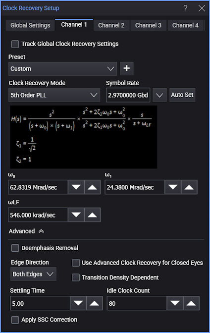
When the 5th Order PLL clock recovery mode is selected, the dialog box has these controls:
-
Symbol Rate — Enter the signal's expected baud rate.
The Select From List drop-down menu lets you select typical rates for standard communication interface technologies. The Auto Set Symbol Rate button runs a data rate measurement and populates the Symbol Rate field with the data rate measured on the input signal.
-
Clock Skew — For PAM type signals, this can be used to center the eye opening at the clock locations by shifting the clocks relative to the data.
-
ω0, ω1, and ωLF:
Note that the following equations use the angular frequency, ω (in radians/sec) which is equivalent to 2πf, where f is frequency (in Hertz).
The Fifth Order PLL's Jitter Transfer Function looks like this:
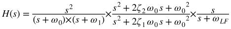
The damping factor parameters are (as with the PCIe Gen 5/6 SRIS and CC Behavioral CDR at 32.0 and 64.0 GT/s):
- ζ1 = 1∕√2
- ζ2 = 1
As an example, the angular frequency parameters for PCIe Gen 5/6 SRIS and CC Behavioral CDR at 64.0 GT/s are:
- ω0 = 10 × 106 × 2π
- ω1 = 3.88 × 106 × 2π
- ωLF = 87 × 103 × 2π