DFE Taps Tab
Click on the DFE operator to open the Decision Feedback Equalizer Setup dialog box with the Taps tab selected.
| Auto Taps | Response Optimization | |
|---|---|---|
| Off | On | |
| On |
|
|
| Off |
|
|
Presets
Presets let you save your dialog box settings to a setup file including any advanced settings. Recall a preset to instantly configure your Decision Feedback Equalizer to your specification. You can save as many presets as you need. If you scroll to the end of the list and click the <Edit List> entry, the Edit DFE Presets List dialog box opens which allows you to reorder, delete, or rename items in the list.
- To save your settings, click the
 button.
 - To recall your settings, click Load.
Common Controls
- Automatic Taps — Lets you select whether tap values are manually entered as comma-, space-, or semicolon-separated values or automatically generated.
-
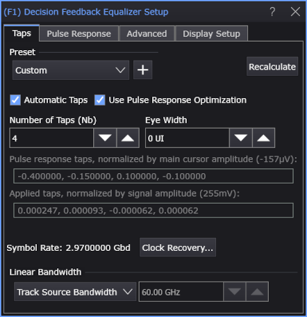
Use Pulse Response or Use Pulse Response Optimization — Lets you use pulse response or pulse response optimization within the DFE.
When these options are selected, the Pulse Response tab appears; it lets you adjust the pulse delay, adjust the pulse length, and save the pulse response after optimize. See DFE Pulse Response Tab.
- Clock Recovery... — Opens the Clock Recovery Setup dialog box where you can specify the signal's symbol rate.
-
Bandwidth — Lets you specify the bandwidth of the low-pass filter that is applied to the DFE threshold waveform prior to summing it to the unequalized waveform.
- Manual — Lets you enter the low-pass filter bandwidth.
- Track Source Bandwidth — The low-pass filter bandwidth is 0.75 times the Nyquist bandwidth of the source.
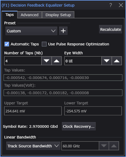
Automatic Taps
When Automatic Taps is selected, the specified number of tap values are automatically generated and displayed in the dimmed Tap Values fields.
- Recalculate — Click any time to regenerate the automatic taps based on the current input waveform.
- Number of Taps (Nb) — You can specify the number of taps used from 1 to 80 taps.
-
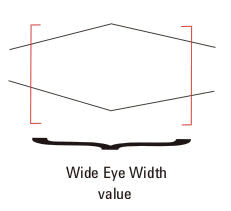
Eye Width — Specifies the percentage of the unit interval, centered on the clock location, to optimize taps for.
You can enter values from zero to one. For example, if the eye width is set to zero (0), taps are optimized for only the voltage specifically at the clock location of each unit interval. If the eye width is set to 0.2, taps are optimized for the voltage in 20% of the unit interval centered on the clock location. If the eye width is set to one (1), taps are optimized for voltage in the entire unit interval.
-
Typically with FFE, the receiver samples data not only at the location of the clock, but also in its vicinity. The default is set to 0.333 UI (unit interval) to account for this variance in the sample location. Typically values between 0.0 UI - 0.5 UI are the most useful.
-
For DFE, true receivers sample data only at the location of the clock, so a value of 0.0 UI (unit interval) is used as the default. If you want to include more of the eye, simply set this number to a higher value (0.0 UI - 0.5 UI would make sense for DFE).
The jitter of the clock relative to the data will affect the eye width you should choose. If you have no jitter, you can choose an eye width of zero (0) because the data waveform will always be sampled at exactly the right time. If you want to accommodate some jitter, choose a higher eye width.
If you are unsure about what value to enter here, but do not want to use the default, think about whether you have more margin vertically or horizontally (where is your uncertainty?). If you optimize the tap values for a narrow portion of the unit interval, your eye will have a greater peak, but only near its center.
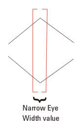
If you optimize the tap values for more of the unit interval, your eye will not be peaked as high, but will be more spread out horizontally.
-
- Tap Values — Shows the automatically generated unitless tap values.
- Tap Values (Volt) — Shows the automatically generated tap values in voltage.
-
Upper Target, Lower Target — These fields show the high and low logical values used in the DFE algorithm.
For example, in DFE, when a bit is determined to be a logical high, its value will be equal to the Upper Target. Similarly, if a bit is determined to be a logical low, its value will be equal to the Lower Target.
When Use Pulse Response Optimization is selected:
- The automatically generated pulse response taps, normalized by main cursor amplitude, are displayed
- The automatically generated applied taps, normalized by signal amplitude, are displayed instead of the Tap Values fields and the Upper Target and Lower Target.
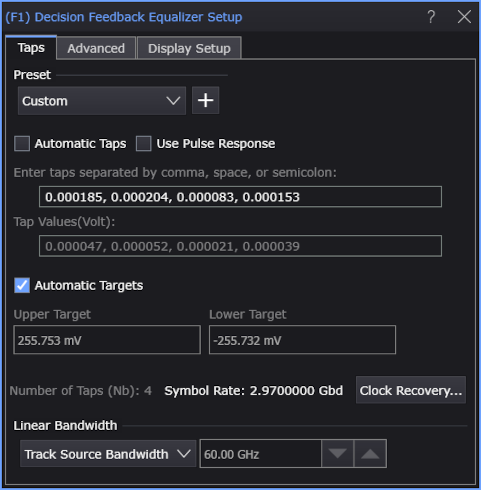
Manual Taps
To manually enter the tap values, clear Automatic Taps and enter your tap values. Separate each value using a comma, space, or semicolon.
To determine the necessary number of taps, refer to the block diagram or hardware DFE in DFE (Decision Feedback Equalizer) Operator.
- Automatic Targets — This option appears when Automatic Taps and Use Pulse Response are cleared. When Automatic Targets is selected, the upper and lower targets in the DFE algorithm are automatically determined. To edit the upper and lower target values, clear Automatic Targets.
-
Upper Target, Lower Target — These fields specify the high and low logical values used in the DFE algorithm.
For example, in DFE, when a bit is determined to be a logical high, its value will be equal to the Upper Target. Similarly, if a bit is determined to be a logical low, its value will be equal to the Lower Target.
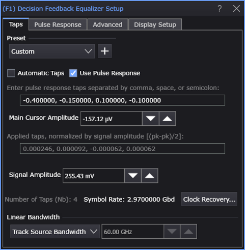
When Use Pulse Response is selected, you can enter the values for:
- Main Cursor Amplitude — Lets you enter the main cursor amplitude that pulse response taps are normalized to.
- Signal Amplitude — Lets you enter the signal amplitude, (pk-pk / 2), that applied taps are normalized to.