DFE (Decision Feedback Equalizer) Operator
 The Decision Feedback Equalizer (DFE) is a form of non-linear equalization which relies on decisions about the levels of previous symbols (high/low) to correct the current symbol. This allows the DFE to account for distortion in the current symbol that is caused by the previous symbols. Its main advantage over linear equalizers is the ability to cancel inter-symbol interference (ISI) without amplifying the noise. The DFE operator lets you validate hardware DFE designs and observe their effects on eye openings.
The DFE's taps are applied to normalized 1/−1 voltages based on a symbol slicer decision. The tap values are meant to correct for the portion of their symbol that lingers and distorts the current symbol.
Before constructing your DFE, drag an output function color to your filter so that you can simultaneously view the input and output waveforms as you develop your equalizer.
The Decision Feedback Equalizer operator requires a single-valued waveform, as opposed to an eye diagram. Be sure that your trigger setup results in a single-valued waveform at the input to this operator.
DFE and Jitter
You can view the effects of the DFE in eye diagrams or with jitter measurements. Eye diagrams are meant to be more qualitative while Jitter measurements have accurate quantitative amplitude measurements, including BER bathtub estimation. With Jitter measurements, amplitude graphs and amplitude scalar measurements (with the exception of BER measurements) can be made on the DFE operator's output waveform. However, jitter graphs and jitter scalar measurements are not compatible with the DFE operator. This is because the threshold transitions are placed at the symbol edges and such discontinuities make the jitter measurements invalid.
About Hardware DFEs
The DFE calculates a correction value that is added to the logical decision threshold. The logical decision threshold is the threshold above which the waveform is considered a logical high and below which the waveform is considered a logical low. As a result, the DFE shifts the threshold up or down so new logical decisions can be made on the waveform based on this new equalized threshold level.
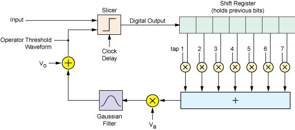
Block Diagram of Hardware DFE
About The DFE Operator
To display the DFE's effect on an eye diagram, the DFE operator subtracts the correction factor from the input waveform and keeps the slicer threshold constant. The slicer results are equivalent to those of the hardware DFE.
Block Diagram of DFE Operator
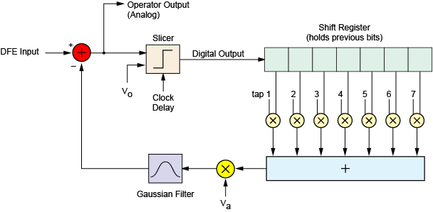
The DFE block diagram has the components:
- Slicer
- The slicer takes a clock delay, an offset voltage (Vo), and the input signal as its inputs. It places its decision point at the center of the symbol, and is then offset from there by the clock delay. Finally, it outputs ±1 based on whether the input voltage at the decision point is above or below the offset voltage.
- Vo
- This is the offset voltage of the input signal before it is corrected.
- Va
- This is the amplitude of the input signal.
- Gaussian Filter
- The Gaussian filter cutoff frequency defaults to the symbol rate but can be manually set up to 1 THz.
Tap Conversions From Other Systems
DFE taps from Keysight real-time scopes can be used directly. Taps from Advanced Design System (ADS) must be scaled by −1/Va (where Va is the input signal amplitude).