Manual Line Markers
Use manual line markers on eye diagrams (multi-valued waveforms). Manual line markers measure the position or magnitude of any location on the display and not just a point on a waveform.
Although manual line markers can be used (in the Waveform, Time-Ohms, Time-Volts, and Time-% waveform content windows only) they are of minimal value. Instead, use Tracking markers. Manual line markers can never be placed on Freq-Mag, Phase, or GrpDelay waveform content windows in any measurement mode.
Manual line markers can be placed only on waveforms that are displayed in a Waveform waveform content window. Manual line markers cannot be placed on Freq-Mag, Phase, GrpDelay, Time-Ohm, Time-Volts, or Time-% waveform content windows. These content windows are displayed when an FFT function's output is defined as some type other than Linear Magnitude. In these instances, use a tracking marker.
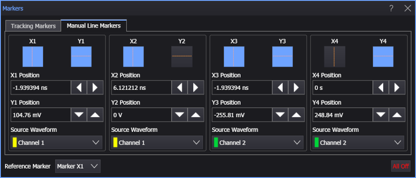
The Markers dialog box controls four sets of markers, which allow you to measure the time and amplitude difference between any two waveform locations:
 Click this button to select one of four X Manual markers. X Manual markers can be positioned independently anywhere on the display. X-axis markers ( vertical lines) measure the time delay from the trigger point. When more than one X-axis markers is turned on, Δ (delta) values between the markers are shown. Depending on the relative position of the markers, the Δ value can be calculated as a negative number, which can result in negative time interval measurements.
 Click this button to select one of four Y Manual markers. Y Manual markers can be positioned independently anywhere on the display. Y-axis markers (horizontal lines) measure the amplitude with respect to the corresponding source ground. Y-axis markers, unlike tracking markers, do not follow the source waveform. When more than one Y-axis marker is turned on, the Δ value between the markers is shown which is useful for voltage or power measurements.
Using Manual Line Markers
To turn a marker on, click one of the eight available manual line marker buttons (X or Y) so that it turns blue. Select the Source Waveform on which to place the marker.
Manual line markers are available for eye diagram waveforms.
You can simultaneously use both tracking markers and manual line markers. However, turning on a tracking marker disables the associated manual line markers. For example, turning on tracking marker 2 disables manual markers X2andY2.
 To move a displayed marker:
-
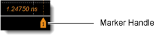
Simply drag the marker line or marker handle
 . Depending on the display window view, the marker handle may not be visible. For exact marker positioning, enter the marker value directly in the Markers dialog box.
 -
You can also move markers using the oscilloscope front-panel Marker Position knobs. When multiple markers are displayed, pushing the horizontal Marker Position knob selects an active X marker for positioning. Repeatedly push the Marker Position knob to move through all active X markers. The vertical Marker Position knob works the same way. See Oscilloscope Front Panel Marker Controls.
Reference Marker and Markers Table
When multiple markers are turned on, you can measure the time and magnitude difference between any two waveform locations. The first marker turned on becomes the reference marker, and the position of all subsequent markers is measured relative to the location of the reference marker.
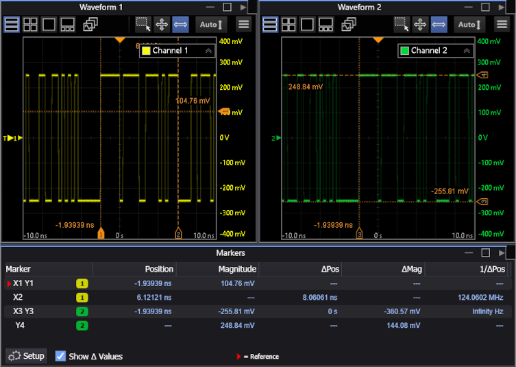
As shown in the above picture, the selected marker(s) have a solid handle background and, in the Markers table, the reference marker is identified by the  icon.
icon.
To show or hide the Δ Pos (delta position), Δ Mag (delta magnitude), and 1/Δ Pos (reciprocal of delta position) values in the Markers table, select Show Δ Values.
Click Setup to open the Markers dialog box.
To change the reference marker:
- Use the dialog box's Reference Marker field.
- In the Markers table, click the marker entry beneath the table's Marker heading.
Marker values are based on the units of the source waveform. The marker resolution is limited to the resolution of the display.
When directly entering marker values, you can position the markers beyond the vertical and horizontal limits of the display graticule. Turn the marker knob or click the dialog box position arrows to set the marker to the edge-of-screen value.
If you adjust the waveform's horizontal position, the X markers will move with the waveform, and the marked position value does not change, even if the marker is moved off the screen.
The marker buttons are also enabled whenever Histogram Windowing or Mask Test Scaling is enabled. You can then use the marker knobs to adjust the marker lines.