Data TIE
 To measure Data TIE (Time Interval Error), Clock Recovery must be performed to determine the clock locations.
Once the clock locations are determined, midpoints between clock locations are compared to edge crossings at the measurement threshold. Differences from the measured edge location and ideal edge location are computed. The following figure shows how the Data TIE is measured.

When measuring over the waveform, the Data TIE measurement is made on all the cycles of the waveform including any cycles that are not in the waveform window. When measuring in a region, the Data TIE measurement is made on all the cycles inside the region only.
Configurable Measurement Parameters
This measurement is affected by the following settings (choose Measure > Thresholds...):
- Thresholds tab
To measure
- Click the toolbar's Data tab.
-
Click the Data TIE button to open the Data TIE dialog box.
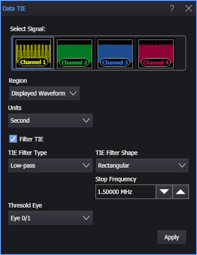
- Select the signal on which to make the measurement.
- Select the Region in which to make the measurement:
- Displayed Waveform — is what you see in the waveform window (which can be a zoomed-in view of the complete waveform).
- Entire Waveform — specifies the complete waveform.
- Region N — If regions are enabled for the selected signal, you can select one of those regions.
- Select the measurement units as either Second or Unit Interval.
-
If you want to apply a filter to the TIE measurement, select Filter TIE. Then, specify the filter parameters using these controls:
-
TIE Filter Type — Selects Low-pass, Band-pass, or High-pass.
-
Start Frequency — Frequencies below this value are filtered out of the TIE measurement.
-
Stop Frequency — Frequencies above this value are filtered out of the TIE measurement.
-
TIE Filter Shape — You can select from these TIE filter edge shapes:
-
Rectangular — The TIE filter is a brickwall filter.
-
20dB/Decade — The TIE filter edge(s) roll off at 20 dB per decade.
-
40dB/Decade — The TIE filter edge(s) roll off at 40 dB per decade.
-
60dB/Decade — The TIE filter edge(s) roll off at 60 dB per decade.
-
First Order — Available with the High-pass and Low-pass filter types only, this is similar to the 20 dB per decade roll off, but the response is more curved. See:
-
Second Order — Available with the High-pass and Low-pass filter types only, this is similar to the 40 dB per decade roll off, but the response is more curved. See:
- Equation for the Second Order High-pass TIE filter
- Equation for the Second Order Low-pass TIE filter
When the Second Order TIE filter edge shape is selected, you an also specify the Damping Factor:
< 1 underdamped > 1 overdamped = 1.0 critically damped = 0.707 Often considered ideal or optimal because of its fast settling time (optimally flat) and Butterworth type response.
-
-
-
If the selected signal is a PAM signal type, use the Threshold Eye selection to specify which eye threshold will be used to make the measurement.
For example, for PAM4 you can select Eye 0/1, Eye 1/2, or Eye 2/3.
-
Click Apply.
SCPI Command
:MEASure:DATA:DTIerror