Real-Time Eye
Performing measurements on eye patterns can provide information about a communication signal's integrity. An eye diagram can show problems with the physical quality of the signal. For example, an eye diagram can tell you if a signal that should correspond to a logical one is so degraded that a receiver will mistake it for a logical zero.
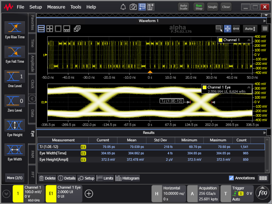
The following screen shows a waveform, its real-time eye view, and measurements being made on the real-time eye.
Real-Time Eyes and traditional eye diagrams differ in that traditional eyes are formed by overlapping multiple acquisitions on top of each other, while real-time eyes are formed by "folding over" a single deep acquisition. When combined with mask testing and there are mask violations, you can unfold the eye to see the waveform where the violation occurred.
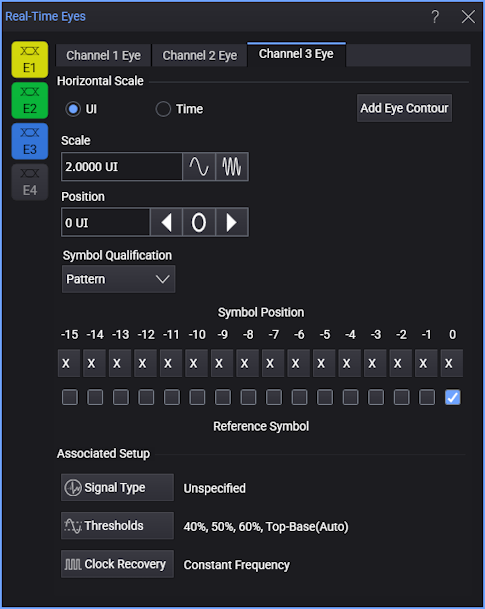
You can enable the real-time eye view by choosing Setup > Real Time Eye... from the main menu. Then, in the Real-Time Eyes dialog box, you can click the corresponding eye button (for example, E1 in the following picture).
The real-time eye display is created by overlapping each unit interval in your serial data stream with respect to the recovered clock (see Clock Recovery). This allows for the one-zero combinations to build up over time and form an eye pattern.
When viewing a real-time eye, the persistence view shows where the waveform is spending most of its time: the screen is never "wiped clean", but instead new traces are drawn over previous ones.
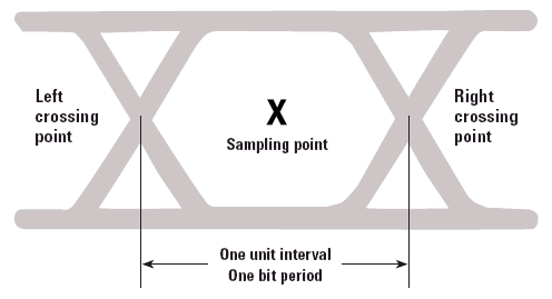
Below is an idealized example of an NRZ (Non-Return to Zero) signal eye diagram showing the unit interval and the crossing points.
This real-time eye display is useful in making eye pattern measurements. See Eye Measurements, and .
For a description of the real-time eye options, see Real-Time Eyes Dialog Box.
Eye Contour Lines
Advanced Eye includes the ability to draw eye contour lines on NRZ and PAM eye diagrams as shown in the picture below. Eye contours provide additional insights into the quality of an eye diagram. Contour lines are scaled to BER. They mark the border within an eye where a specific fixed Symbol Error Ratio (BER) occurs. The following picture shows two contour lines on Channel 1. One line marks the 1.0 x 10⁻⁹ border and one line marks the 1.0 x 10⁻¹⁵ border. On Channel 2, contour lines are placed on all three eyes of the PAM waveform. With eye contours, you can create the following items:
- Up to 16 groups of lines placed on any displayed eye diagram.
- Each group can contain up to eight individual contour lines.
- Multiple eye contour groups can be placed on the same eye.
- When applied to a PAM waveform, the group's lines are displayed within each of the three eye openings.
- An Eye Contours legend is displayed next to the waveform and identifies each contour line.
To create a group of eye contour lines
- Click the Add Eye Contour button in the Real-Time Eyes dialog box to open the Eye Contour Group Setup dialog box.
- Select the source waveform and contour lines and then close the dialog box.
To edit an existing eye contour group or to move it to a different waveform
- Click on the group in the Eye Contour table to select the group.
- Click Setup, which is located beneath the table to open the Eye Contour Group Setup dialog box. The dialog box is populated with the current settings of the selected group. Make any needed changes, including source waveform, and close the dialog box.