Analyzing Data on Trace Using Marker
Other topics about Data Analysis
The marker can be used in the following ways:
-
Reading a measured value as numerical data (as an absolute value or a relative value from the reference point)
-
Moving the marker to a specific point on the trace (marker search)
-
Using the value of the marker to change the stimulus (sweep range) and scale (value of the reference line)
For more information, refer to Searching for Positions that Match Specified Criteria.
For the procedure used to change the sweep range and scale by using the marker, refer to Specifying Sweep Range by Using Marker.
The E5052B is capable of displaying up to 10 markers (10 normal markers or 9 normal markers and 1 reference marker) on each trace. Each marker has a stimulus value (the value on the X-Axis) and a response value (the value on the Y-Axis).
You can read the value of a marker displayed on the trace.
You can set the marker for the selected measurement window.
The marker response value is always in the same data format as that of the Y-Axis.
-
Press Trace Next or Trace Max to activate the trace on which you want to use the marker.
-
Press Marker. At this point, marker 1 is turned on and becomes active (you can operate the marker). When using marker 1, you can omit Step3.
-
Select a marker and turn it on. The softkey used to turn on a marker is used to activate that marker.
-
Change the marker value in the entry area. This operation enables you to move the marker to a point on the desired trace.
The marker value in the entry area can be changed by one of the following methods.
-
To change the value in the entry area, the figure in the box should be highlighted. If the figure is not highlighted, press the softkey for the marker you are using (marker 1 to marker 10) or Focus to highlight the figure.
-
-
Enter a numeric value using the ENTRY block key on the front panel.
-
Turn the rotary knob  on the front panel.
-
Press the up or down arrow key (
( ) on the front panel.
-
Using the mouse, click one of the buttons ( 
 ) on the right side of the entry area.
You can move the marker by dragging and dropping either one of the marker position pointers above or below the graph ( ) (pressing the button on the object to be moved and releasing the button on the destination). You can also move a marker itself by dragging and dropping it.
-
When using other markers, repeat Step3 and Step4.
Read the marker stimulus value and marker response value displayed in the upper part of the trace screen.
To turn off marker(s), press the Clear Marker Menu and then select the desired softkeys.
|
|
|
|
All OFF
|
Turns off all markers on active trace
|
|
Marker 1 to Marker 10
|
Turns off one of markers 1 through 10 on active trace
|
You can change the display position of the marker value on the graph.
Operational Procedure
-
Press Trace Next or Trace Max to activate the trace on which you want to use the marker.
-
Press Display.
-
Press Marker Information to change the display position.
|
|
|
|
Left
|
Displays marker value in upper-left part of graph
|
|
Right
|
Displays marker value in upper-right part of graph
|
You can also view the marker values in a list. For more information, refer to Listing All Marker Values in All Displayed Traces.
You can copy the active marker value to the position of start, stop or center. If multiple markers are present on the active trace, only the active marker can be moved.
For TR Measurement: Marker to Target Frequency and Phase reference can be set using Marker --> > Marker -> Target Freq (or N2 Target Freq)and Marker --> > Marker -> Phase Reference (or N2 Phase Reference). For more information on phase reference, refer to Using the phase reference frequency.
-
For AM / BB / PN / PS Measurement: An additional marker option is available at Marker --> > Marker -> Omit Spur.
It is recommended to use this function with the Discrete value ON as:
Marker > More functions > Discrete > ON. When it is used this function with Discrete > Off, it is possible to specify the frequency data that is not effective at omit of the specific Spurious.
In Omit Spur option, when X-axis data of Spurious List is not within the X-axis for Trace Data, the data equivalent to outside of scope is ignored. For information on Omit Spur, refer to Setting Omit Specified Spur.
Operational Procedure
-
Press Trace Next or Trace Max to activate the trace on which you want to use the marker.
-
Press Marker -->.
-
Press the corresponding softkey to specify the sweep range.
Reading Relative Value From Reference Point on Trace
You can convert the marker reading to a relative value from the reference point.
Reference Marker Mode
Operational Procedure
-
Press Trace Next or Trace Max to activate the trace on which you want to use the marker.
-
Press Marker.
-
Press More functions .
-
Press Ref Marker to specify the reference marker (Marker 1 through 10).
By default, marker 1 is set as the reference marker.
-
Press Ref Marker Mode to turn on the reference mode.
Activate the reference marker if it is not active.
With the reference mode turned on, the stimulus values and response values are indicated in relative values referred to by the position of the reference marker.
Following Step4in Reading Values on Trace, place the reference marker on the point to be used as the reference.
Following Step3to Step4in Reading Values on Trace, place markers 1 through 10 on the desired points to read the values.
To use the list view of the marker values, refer to Listing All Marker Values in All Displayed Traces.
The point on the trace on which a marker can be placed differs depending on how the discrete marker mode is set up.
|
|
|
|
Turning on discrete mode
(Discrete ON)
|
A marker moves only between actual measurement points. When a specific marker stimulus value is specified as a numerical value, the marker is placed at the measurement point closest to the specified value. A marker that is placed between interpolated points with the discrete mode off automatically moves to the nearest measurement point when the discrete mode turns on.
|
|
Turning off discrete mode
(Discrete OFF)
|
The marker can move from one actual measurement point to another. Because it is interpolated, it can also move in the space between measurement points.
|
Marker Discrete Mode
Operational Procedure
-
Press Trace Next or Trace Max to activate the trace on which you want to use the marker.
-
Press Marker.
-
Press More functions.
-
Press Discrete to turn the discrete mode ON or OFF.
Setting Up Markers for Each Trace/Setting up Markers for Coupled Operations Between Traces
Markers can be set up and moved either in a coupled operation for all traces in a channel or independently for each trace.
You can set up marker coupling for frequency/power measurement, transient measurement and the user window.
Marker Coupling
|
|
|
|
Marker Couple is on
(Couple ON)
|
Markers are set up and moved in coupled operation on all traces in a channel.
|
|
Marker Couple is off
(Couple OFF)
|
Markers are set up and moved independently for each trace.
|
Operational Procedure
-
Press Trace Next or Trace Max to activate the trace on which you want to use the marker.
-
Press Marker.
-
Press Couple to turn the marker coupling on or off.
-
For the transient measurement, both the marker coupling (Couple) and the marker discrete mode are turned on, where the active marker on the active trace operates in the discrete mode; however, the other subsequent markers are not always on the measurement point, since they are coupled with the value.
You can list all of the marker values for all traces on the marker list display.
Operational Procedure
-
Press Marker.
-
Press Marker List to turn on the marker list display.
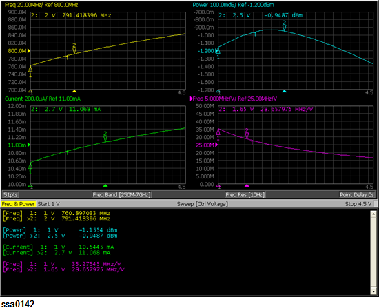
The marker list is displayed in the lower part of the screen as shown in the following figure.
Turning on Marker List