Setting Phase Noise Measurement
Follow the steps below to measure the phase noise by using the E5052B’s phase noise measurement window.
-
Press Meas/View > Phase Noise to select the phase noise measurement window.
-
You can maximize the phase noise measurement window by pressing the Window Max key while the window is selected. You can return to the original size when you press the Window Max key once again.
-
Press Setup > Capture Range > Normal for PLL method.
-
Press Setup > Capture Range > Wide for Discriminator method.
If the DUT response is drifting or noisy, the E5052B cannot lock the signal using PLL method. In such cases, use Discriminator method technique.
The drift should be typically smaller than both of the following limitations:
-
Normal: 40 kHz/20 msec, 0.4% of carrier frequency
-
Wide: 2 MHz/sec, 0.4% of carrier frequency
-
PLL and Discriminator are the two types of methods available in E5052B. PLL is the default capture range setting. When Capture Range is Wide, it is possible to measure from 250MHz. In order to change the frequency range, it is recommended to change the capture range to PLL method.
For more details on PLL method and discriminator method, refer to Overall Instrument Operation.
The switch reference signal option is available in both phase noise measurement and segment phase noise measurement that enables you to select as channel 1 (CH1) and channel 2 (CH2). Normally in both phase noise measurement and segment phase noise measurement, CH1 is set to internal, and CH2 is set to external and then reference signal provided from CH2 is distributed to CH1 internally. For other measurement modes, CH1 is set to internal, and CH2 is set to external.
Follow the steps below to switch reference signal:
-
Press Meas/View > Phase Noise
-
Press Setup > Reference Oscillator > Bandwidth > Narrow | Wide
-
The selection of Narrow/Wide is for the Bandwidth of Reference Oscillator of PLL.
-
Press Setup > Ref. Osc.1 Source > Internal | External
-
Press Setup > Ref. Osc.2 Source > Internal | External
-
When reference source is Internal, Internal Oven Controlled Crystal Oscillator signal is used as reference signal.
External input signal is used as reference when the source is External. If E5052B cannot recognize the External input signal, it will automatically select Internal signal as the reference source.
-
Press Setup > Frequency Band.
-
Select the appropriate frequency band that contains the target carrier signal from the softkey menu list. The range of each frequency band is listed in the following table.
"IF over flow" error may be displayed when phase noise is distorted. On the other hand, internal noise level of the instrument may be significant in the measurement display when the DUT has a low-noise characteristics. In this case, follow the steps below to adjust the IF Gain value.
-
Press Setup > IF Gain.
-
Enter the IF Gain value in the data entry field that appears in the upper part of the screen.
You can select the value from the options: 0 dB, 10 dB, 20 dB, 30 dB, 40 dB or 50 dB.
IF Gain and PLL BW
|
|
|
|
|
Carrier frequency is less than or equal to 100 MHz
|
PLL BW = 1 kHz
|
PLL BW = 1 kHz
|
|
Carrier frequency is greater than 100 MHz
|
PLL BW = 5 kHz
|
PLL BW = 350 Hz
|
-
When either “Phase lock loop unlocked” or "IF A/D overflow" error message is displayed, choose an appropriate IF Gain value as indicated in the table below.
IF Gain selection table
|
|
|
|
Frequency drifting sources
(Free-run VCO, etc.)
|
0, 10 dB
|
|
Frequency locked sources
(PLL Synthesizer, etc.)
|
20, 30, 40, 50 dB
|
-
With the Option 011 configured, available IF Gain options are 0 dB, 10 dB, 20dB and 30 dB.
-
If the IF signal is not at appropriate value a “drop out” may occur as it will not be able to detect the phase noise of the DUT at the ADC resulting in strange measurement as shown in the figure below.
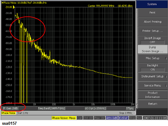
In such case, it is recommended to increase the value of IF gain (default value of 20dB) as it is important to correctly measure the phase noise at close in offset.
From firmware rev A.3.10, Frequency band, Input Attenuator and IF Gain can be set to optimum value according to input signal through an automatic setting.
-
Enables when you selected Trigger to Phase Noise.
-
Press Setup > Auto Setting.
-
Carrier frequency band, Attenuator and IF Gain should be set to optimum value according to input signal.
Auto setting Parameter at each measurement status as follows.
|
|
|
|
|
|
Downconverter=Off
|
Y
|
Y
|
Y
|
|
Downconverter=On, RF Input=E5052B Direct
|
Y
|
Y
|
Y
|
|
Downconverter=On, RF Input=Downconverter, Ext.Mixer=Off
|
User set
|
10dB
|
Y
|
|
Downconverter=On, RF Input=DownConverter, Ext.Mixer=On
|
N
|
N
|
N
|
|
|
|
|
|
|
Downconverter=Off
|
Band4
|
Y
|
N
|
|
Downconverter=On, RF Input=E5052B Direct
|
Band4
|
Y
|
N
|
|
Downconverter=On, RF Input=Downconverter, Ext.Mixer=Off
|
User set
|
10dB
|
N
|
|
Downconverter=On, RF Input=DownConverter, Ext.Mixer=On
|
N
|
N
|
N
|
-
When one of the following error messages is displayed, please try to set the wide capture mode (Press Setup > Capture Range > Wide).
"130 Auto setting failed"
"133 Failed to find IF gain"
"132 Try wide capture range"
When "IF A/D overflow" is displayed, please try to decrease 10 dB from the current IF Gain setting (Press Setup > IF Gain).
-
The auto setting function of the E5052B does not change capture range from the normal capture range to wide capture range automatically. When the carrier frequency is less than 250 MHz or the DUT is noisy (or drifty) while the auto setting is being executed, a message "132 Try wide capture range" is displayed.
Enter the nominal value of the carrier frequency.
-
Press Setup > Nominal Frequency.
-
Enter the value of the nominal frequency in the data entry field displayed in the upper part of the screen.
-
You need to specify nominal frequency only when the downconverter is available.
-
The carrier search function is to detect the input signal frequency with the selected carrier frequency band for the downconverter RF IN (i.e. 3 to 10 GHz or 9 to 26.5 GHz) and reflect the result to the nominal frequency.
See also Executing Carrier Search Function.
In the SSB phase noise measurement of the DUT, LO phase noise characteristics can be selected for optimizing the phase noise measurement accuracy.
-
Press Setup > LO PhNoise Optimize.
-
Select LO phase noise characteristics in the softkey menu displayed.
|
|
|
|
L(f) for > 150 kHz
|
Lowering LO SSB phase noise at > 150 kHz offset frequency
|
|
L(f) for < 150 kHz
|
Lowering LO SSB phase noise at < 150 kHz offset frequency
|
-
Press Setup > Measurement Quality.
-
Select the appropriate quality level from the softkey menu list. The available options are Normal and Fast.
-
To obtain the outline of the measurement data, select “Fast” for the quality level. If you need more precise frequency resolution, select “Normal” for the quality level.
The fast mode allows you to do faster measurement than that in the normal mode. The fast mode uses 8 times wider than that in the normal mode at all offset frequency set, while the number of measurement points (Relation Table for Measurement Points and Sweep Range), which is determined by the start and stop offset frequency, are the same between two modes. With the fast mode, the ability to distinguish spurious in frequency gets less precise than that in the normal mode. The default is set to normal mode.
-
Press Start/Center (Stop/Span) > Start.
-
Select the sweep start value from the softkey menu list.
You can select the value from the options: 1 Hz, 10 Hz, 100 Hz or 1 kHz.
-
Press Stop/Span (Start/Center) > Stop.
-
Select the sweep stop value from the softkey menu list.
You can select the value from the options: 100 kHz, 1 MHz, 5 MHz, 10 MHz, 20 MHz, 40 MHz or 100MHz.
-
For PLL Measurement method only the offset frequency is expanded to 100MHz.
Sweep stop values that are selectable differ depending on the selection of the carrier frequency band.
-
-
-
For 10 M - 41 MHz
100 kHz, 1 MHz, 5 MHz
-
For 39 M -101 MHz
100 kHz, 1 MHz, 5 MHz, 10 MHz, 20 MHz
-
For 99M - 1.5GHz
100 kHz, 1MHz, 5MHz, 10MHz, 20MHz, 40MHz
-
-
-
For frequency bands other than above
100 kHz, 1 MHz, 5 MHz, 10 MHz, 20 MHz, 40 MHz, 100MHz
Relation Table for Measurement Points and Sweep Range
|
|
|
|
|
|
|
|
|
|
|
646
|
775
|
865
|
904
|
943
|
982
|
1033
|
|
|
517
|
646
|
736
|
775
|
814
|
853
|
904
|
|
|
388
|
517
|
607
|
646
|
685
|
724
|
775
|
|
|
259
|
388
|
478
|
517
|
556
|
595
|
646
|
In the phase noise measurement for log sweep, the number of correlation pre-defined depends on the start offset frequency. For example, when the start offset frequency is set to 1 Hz, the correlation of 128000 times is executed in offset frequency of 10MHz or more. The specification of the phase noise sensitivity in the datasheet is when the start offset frequency is 1 Hz. Refer to Tables as follows to confirm the effect of the start offset frequency on the phase noise sensitivity.
Start offset frequency : 1 Hz
|
|
1
to
47.7
|
47.7
to
190.7
|
190.7
to
1.53k
|
1.53k
to
12.21k
|
12.21k
to
97.66k
|
97.66k
to
|
781.25k
to
|
6.25M
to
|
|
|
1
|
4
|
32
|
256
|
2048
|
16384
|
32000
|
128000
|
|
|
0
|
3.0
|
7.5
|
12.0
|
16.6
|
21.1
|
22.5
|
25.5
|
Start offset frequency : 10 Hz
|
|
10
to
190.7
|
190.7
to
1.5k
|
1.5k
to
12.21k
|
12.21k
to
97.66k
|
97.66k
to
|
781.25k
to
|
6.25M
to
|
|
|
1
|
8
|
64
|
512
|
4096
|
8000
|
32000
|
|
|
0
|
4.5
|
9.0
|
13.5
|
18.1
|
19.5
|
22.5
|
Start offset frequency : 100 Hz
|
|
100
to
1.5k
|
1.5k
to
12.21k
|
12.21k
to
97.66k
|
97.66k
to
|
781.25k
to
|
6.25M
to
|
|
|
1
|
8
|
64
|
512
|
1000
|
4000
|
|
|
0
|
4.5
|
9.0
|
13.5
|
15.0
|
18.0
|
Start offset frequency : 1 kHz
|
|
1k
to
12.21k
|
12.21k
to
97.66k
|
97.66k
to
|
781.25k
to
|
6.25M
to
|
|
|
1
|
8
|
64
|
125
|
500
|
|
|
0
|
4.5
|
9.0
|
10.5
|
13.5
|
About DC Voltage Setting and Protection
You can specify DC power/control that is applied to DUT. Refer to Setting DC power/DC control and protection for the setting procedure.
About Auto Frequency Control Function
If this function is turned on, the E5052B will adjust the control voltage automatically so that the output signal frequency from the DUT may keep the specified value. For the setting procedure, refer to the Auto Frequency Control Function.