This topic contains the following information:
S-Parameters (pre-selected ratios)
Ratioed (choose your own ratio)
Unratioed Power (absolute power)
Learn about Balanced Measurements
See other 'Setup Measurements' topics
S-parameters (scattering parameters) are used to describe the way a device modifies a signal. For a 2-port device, there are four S-Parameters. The syntax for each parameter is described by the following:
S out - in
out = |
analyzer port number where the device signal output is measured (receiver) |
in = |
analyzer port number where the signal is applied (incident) to the device (source) |
Move the mouse over each S-parameter to see the signal flow:
For two-port devices:
When the source goes into port 1, the measurement is said to be in the forward direction.
When the source goes into port 2, the measurement is said to be in the reverse direction.
The analyzer automatically switches the source and receiver to make a forward or reverse measurement. Therefore, the analyzer can measure all four S-parameters for a two-port device with a single connection.
See the block diagram (including receivers) of your VNA.
Reflection
Measurements |
Transmission
Measurements |
|
|
The standard class has test port receivers and reference receivers.
R1 and R2 are reference receivers. They measure the signal as it leaves the analyzer source.
R1 measures the signal out of Port 1
R4 measures the signal out of Port 2
A and B are test port receivers. They measure the signal out (or reflecting off ) of the DUT.
A measures the signal into VNA Port 1
B measures the signal into VNA Port 2
Models with more than 4 ports must specify receivers using Logical Receiver Notation. Learn more.
Ratioed measurements allow you to choose your own ratio of any two receivers that are available in your analyzer. S-parameters are actually predefined ratio measurements. For example S11 is A/R1.
The following are common uses of ratioed measurements:
Comparing the phase between two paths of a device. An example could be something simple like a power splitter or more complicated like a dual-channel receiver.
Measurements that require a higher dynamic range than the analyzer provides with S-parameters.
The unratioed power parameter measures the absolute power going into any of the receivers that are available on your analyzer.
The reference receivers are internally configured to measure the source power for a specific analyzer port.
Measuring phase using a single receiver yields meaningless data. Phase measurements must be a comparison of two signals.
Averaging for Unratioed parameters is computed differently from ratioed parameters. Learn more.
To calibrate ratioed or unratioed receiver (power) parameters, the recommended method is the Guided Power Calibration. The Unguided Response Calibration can also be used to calibrate a single unratioed or ratioed parameter at a time.
Click a tab to create or change measurements.
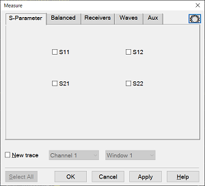
TabsS-Parameter Select a predefined ratioed measurements. Learn more about S-parameters.
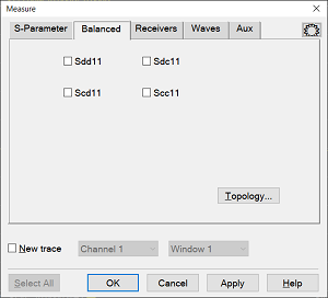
Balanced Select a balanced measurement type.
Topology Click to invoke the Balanced DUT Topology / Logical Port mappings dialog box. Learn more about Balanced Measurements. Select All Will only select the parameters shown and will not select the check box of the Receiver selector at the bottom.
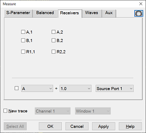
Receivers Select receivers to make Ratioed and Unratioed (absolute power) measurements. Learn more about receiver measurements.
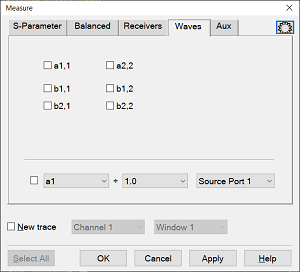
Ratioed Click on the check box to select the parameters and create measurement. Receiver selector at the bottom allow you to define ratios. Select a receiver for the Numerator, select another receiver for the Denominator, then select a source port for the measurement. The Source port is ALWAYS interpreted as a logical port number. For convenience, the table is populated with common choices. Select All Will only select the parameters shown and will not select the check box of the Receiver selector at the bottom. Unratioed Same as Ratioed, but select 1 as the Denominator. Waves Select receiver notation to make ratioed and unratioed measurements.
Click on the check box to select the parameters and create measurement. Wave selector at the bottom allow you to define ratio. Select All Will only select the parameters shown and will not select the check box of the Wave selector at the bottom.
Channel / Window Selections
These selections are NOT AVAILABLE when changing an EXISTING measurement. Learn how to change a measurement. Channel Number Select the channel for the new traces. Create in New Window
About Measurement Parameters (top of page) |
|
|
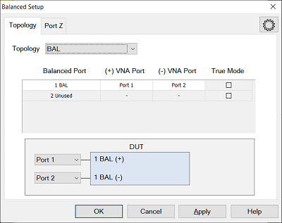
Topology Tab
Create or edit DUT Topology and Logical Port Mapping. A Logical Port is a term used to describe a physical analyzer test port that has been remapped to a new port number. You can assign logical single-ended ports to logical balanced ports. Note: These selections apply to ALL measurements in the channel. If the device topology is changed, any existing measurements in the channel that are incompatible with the new topology will be automatically changed to one that is compatible. Topology: Describes your DUT as you would like it tested.
Balanced Port Number of rows equals number of VNA ports. User may select each port as SE or BAL or Unused. Unused ports are always forced to the bottom of the list and some Unused port selectors may be grayed-out when all the VNA ports are used. VNA Port Displays physical port numbers. But will display logical port numbers if logical ports are used. Balanced port requires (+) and (-) VNA port definitions; SE port only requires a single VNA port definition. True Mode This function is not supported.
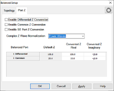
Port Z Tab
Provide an enable for both Common and Differential Conversion and SE Port Z Conversion. Complex Z Wave Normalization
Balanced Port Shows all ports defined on the balanced topology page. Default Z Shows the default impedances that will be applied if the port Z conversions are not enabled. The SE Default Z always equals the System Zo defined for the VNA. The Differential and Common Default Z will display values calculated from the single-ended port impedances. Converted Z User may enter the real or imaginary component of the impedance.
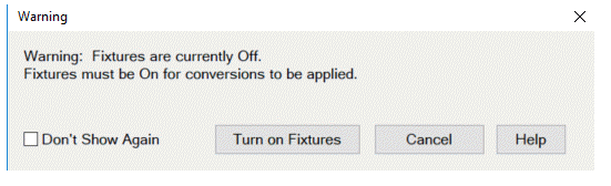
Warning Dialog The dialog is displayed if "Conversion" is enabled and "Apply Fixtures" is currently disabled. See Also
|
|