Reading Actual Measurement Point/Value Interpolated between Measurement Points
Setting up Markers for Each Trace/Setting up Markers for Coupled Operation between Traces
Other topics about Data Analysis
The marker can be used in the following ways:
Reading a measured value as numerical data (as an absolute value or a relative value from the reference point)
Moving the marker to a specific point on the trace (marker search)
Analyzing trace data to determine a specific parameter
Using the value of the marker to change the stimulus (sweep range) and scale (value of the reference line)
For the procedure used to change the sweep range and scale by using the marker, refer to Setting the Sweep Range Using the Marker and Setting the value of a reference line using the marker.
The E5071C is capable of displaying up to 10 markers including the reference marker on each trace. Each marker has a stimulus value (the value on the X-axis in rectangular display format) and a response value (the value on the Y-axis in rectangular display format). The Smith chart and polar formats each have two marker response values (log amplitude and phase).
You can read the value of a marker displayed on the trace.
In rectangular display format, the marker response value is always in the same data format as that of the Y-axis. On the contrary, one format for the marker response values (two values: main and auxiliary) can be selected from among several types. The selection is performed in the data format.
|
Softkey for selecting data format |
Marker response value |
|
|
Main |
Auxiliary |
|
|
Smith - Lin / Phase |
Linear amplitude |
Phase |
|
Smith - Log / Phase |
Log amplitude |
Phase |
|
Smith - Real / Imag |
Real component |
Imaginary component |
|
Smith - R + jX |
Resistance |
|
|
Smith - G + jB |
Conductance |
|
|
Polar - Lin / Phase |
Linear amplitude |
Phase |
|
Polar - Log / Phase |
Log amplitude |
Phase |
|
Polar - Real / Imag |
Real component |
Imaginary component |
For setting up data formats, refer to Selecting a Data Format.
Press Channel Next/Channel Prev keys to activate the channel on which a marker is used.
Press Trace Next/Trace Prev to activate the trace on which a marker is used.
Press Marker key. At this point, marker 1 is turned on and becomes active (you can operate the marker). When using marker 1, you can omit the next step.
Select a marker and turn it on. The softkey used to turn on a marker is also used to activate that marker.
Change the marker stimulus value. This operation enables you to move the marker to a point on the selected trace.
Read the marker stimulus value and marker response value displayed in the upper-left part of the trace screen.
Press Marker key.
Click Clear Marker Menu and then click one of the options.
In the preset configuration, the marker settings on traces in a channel are coupled (Marker Couple is turned on). For marker coupling, refer to Setting up markers for each trace/Setting up markers for coupled operations between traces.
You can convert the marker reading into a relative value from the reference point.
Move the reference marker at the point to be used as the reference.
Click Ref Marker Mode to turn on the reference mode.
With the reference mode turned on, the stimulus values and response values are indicated in relative values referred to by the position of the reference marker.
Activate your desired marker, then move it to your desired position.
Pressing Marker and then clicking Ref Marker enables you to place the reference marker at the position of the currently active marker . The reference mode will then turn on automatically.
The point on the trace on which a marker can be placed differs depending on how the discrete marker mode is set up.
|
Value |
Description |
|
Turning on discrete mode |
A marker moves only between actual measurement points. When a specific marker stimulus value is specified as a numerical value, the marker is placed at the measurement point closest to the specified value. A marker that is placed between interpolated points with the discrete mode off automatically moves to the nearest measurement point when the discrete mode is turned on. |
|
Turning off discrete mode |
The marker can move from one actual measurement point to another. Because it is interpolated, it can also move in the space between measurement points. |
Press Channel Next/Channel Prev keys and Trace Next/Trace Prev to activate the trace on which the discrete mode is set up.
Press Marker Fctn key.
Click Discrete to turn the discrete mode on or off.
Makers can be set up and moved either in coupled operation for all traces in a channel or independently for each trace.
|
Value |
Description |
|
Marker Couple is on |
Markers are set up and moved in coupled operation on all traces in a channel. |
|
Marker Couple is off |
Markers are set up and moved independently for each trace. |
Press Channel Next/Channel Prev keys to activate the channel on which the marker couple will be set.
Press Marker Fctn key.
Click Couple to turn the marker coupling on or off.
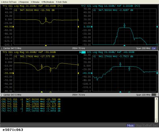
You can list all of the marker values in all of the displayed channels on the screen.
Press Marker Fctn key.
Click Marker Table to turn on the marker table display.
The marker table appears in the lower part of the screen.
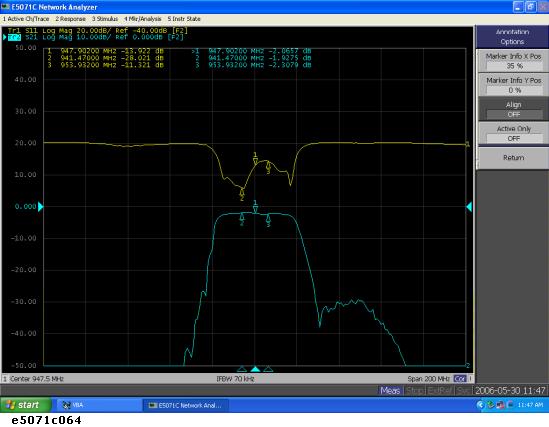
This section describes how to specify the marker value display position for each active trace.
|
Value |
Description |
|
Marker Info X Pos |
Specifies the horizontal display position by the width of the display area as a percentage.
|
|
Marker Info Y Pos |
Specifies the vertical display position by the height of the display area as a percentage.
|
Press Channel Next/Channel Prev keys to activate the channel for which you want to set marker coupling.
Press Marker Fctn key.
Click Annotation Options.
Click Marker Info X Pos to set the horizontal display position.
Click Marker Info Y Pos to set the vertical display position.
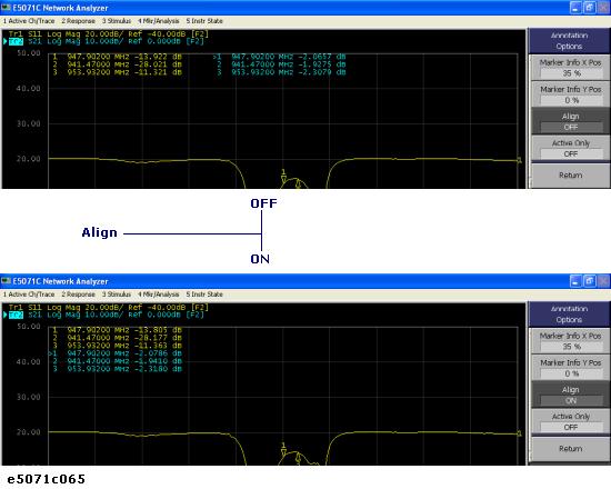
This section describes how to align maker value displays.
|
Value |
Description |
|
On |
Displays marker values to align to the display position of trace 1. |
|
Off |
Displays marker values in the display position defined for each trace. |
Press Marker Fctn key.
Click Annotation Options.
Click Align to toggle ON/OFF.
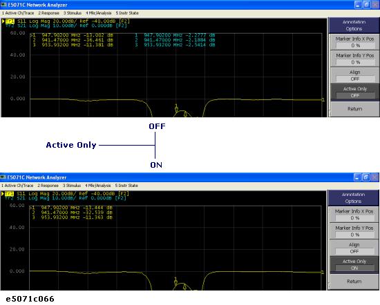
This section describes how to display all marker values for displayed traces.
|
Value |
Description |
|
Displays all |
Displays all marker values for displayed traces. |
|
Displays active markers |
Displays markers for the active trace only. |
Press Marker Fctn key.
Click Annotation Options.
Click Active Only to toggle ON/OFF.