Click on an area of the image to learn more.
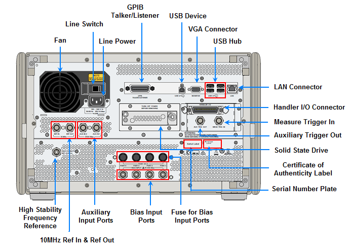
The cooling fan for controlling the temperature inside the VNA. This fan exhausts heated air from inside the analyzer to the outside.
This switch must always keep it ON ( | ).
Caution: Do not use this switch to turn off (O) the mains. Doing so may cause the VNA to fail. For more information, see the description of the Line Power.
The receptacle to which the power cable is connected.
Note: To connect the device to a power source (outlet), use the supplied three-prong power cable with a ground conductor. The plug attached to the power cable (on the power outlet side or device side of the cable) serves as the disconnecting device (device that cuts off power supply) of the VNA. The power supply must be cut off to avoid such danger as electric shock, pull out the power cable plug (on the power outlet side or device side of the cable). For the procedure for turning off the mains in normal use, see the description in Power Switch.
When a 10 MHz external reference signal is detected at this port, it will be used as the instrument frequency reference instead of the internal frequency reference.
Notes: When the external frequency reference signal is input to this connector, the measurement signal from the VNA is automatically phase-locked to the reference signal. When an input signal is not present, the frequency reference signal inside the VNA is automatically used. The ExtRef on the instrument status bar is displayed in blue when the system is phase-locked to the external reference signal and in gray when not phase-locked.
When using Option 1E5 (high stability frequency reference), connect this connector to the High Stability Frequency Reference Output Connector (Ref Oven, Option 1E5 only) by using the BNC(m)-BNC(m) cable included with the option.
|
Specification |
Value |
|
Connector type |
BNC(f) connector |
|
Input signal |
10MHz ± 10ppm, - 3 to + 10 dBm |
See SCPI command that detects an external reference signal at this connector.
A connector for outputting the internal frequency reference signal from the VNA in order to use by others test equipment. By connecting this output connector to the external reference signal input connector of another device, the device can be phase-locked to the internal reference signal of the VNA and used under this condition.
|
Specification |
Value |
|
Connector type |
BNC(f) connector |
|
Output signal |
10MHz ± 5ppm, 0 dBm ± 3dBm |
|
Output impedance (Typical) |
50 ohm |
When Option 1E5 (high stability frequency reference) is installed, the reference signal is output from this connector. See Specifications
|
Specification |
Value |
|
Connector type |
BNC connector, female |
|
Output signal (Typical) |
10MHz ± 1ppm, 0 dBm minimum |
Note: When Option 1E5 (high stability frequency reference) is installed, connect this connector to the External Reference Signal Input Connector (10MHz Ref In) by using the BNC(m)-BNC(m) cable included with the option.
The Auxiliary Input Ports are used to input DC signal for DC signal measurement.
The VNA can be a GPIB Controller and Talker/Listener.
The connection of an external controller through GPIB connector allows you to configure an automatic measurement system. This GPIB connector is used only for controlling the VNA from an external controller. Use USB/GPIB interface to control other devices from the VNA. You cannot control other devices from the VNA through this GPIB connector. Learn more.
Through this port, you able to control the VNA from external controllers. For more information on the measurement system using the USB port, see the Remote Control of SCPI USB Devices Connected to a VNA.
|
Specification |
Value |
|
Connector type |
Universal serial bus (USB) jack, type B (4 contact positions), Female |
|
Compliance Standards |
USBTMC-USB488 and USB2.0 |
Learn more
A terminal which an external color monitor (display device) can be connected. By connecting a color monitor to this terminal, the same information shown on the LCD touchscreen of the main body can be displayed on an external color monitor.
This USB hub contains four USB ports to power VNA peripherals. There are also four USB ports on the front panel.
The four USB are provide that can use for connecting to ECal (Electronic Calibration) module, USB, Multiport test set or a printer. Connecting a designated ECal module to this port enables ECal measurements to be taken. Connecting a compatible printer to this port enables screen information on the VNA to be printed.
Limitation: The total power consumption for all eight USB ports is limited to 4.0 amps. If this limit is exceeded, all USB ports are disabled until a device is removed and power consumption falls below the limit. When first connected, ECal modules 8509x and N4431 draw significantly more current than other modules. See Specifications.
See Important First-time USB connection note.
A terminal for connecting the VNA to a LAN enables you to access the solid state drive of this instrument from an external PC or to control this instrument by using SICL-LAN or telnet.
This 10/100Base-T Ethernet connection has a standard 8-pin configuration and auto selects between the two data rates.
The terminal which is an automatic machine (handler) used on a production line is connected. See details.
When enabled, VNA is triggered by signals on this connector.
A connector to which measure trigger signals are input. This connector detects the downward transition from the HIGH state in TTL signals as the trigger signal. To use this connector to generate a trigger, you must set the trigger source to "external" (key operation: Trigger > Main > Trigger Source > External).
Connector type: BNC connector, female. Learn more.
When enabled, VNA outputs signals on these connectors either before or after a measurement. Learn more.
There are two options for SSD.
Non removable SSD option.
Removable SSD option
See Service Guide to learn how to remove the SSD. (Internet connection required)
See Preventing VNA Solid State Drive Problems
The label showing the information of the Certificate of Authenticity of Windows.
The label showing the product number, serial number and the installed option number. The accessary and system rack options are not listed on this label. (CFGxxx or ATOxxx in the first line is for Keysight Use Only.)
This BNC female connector allows external bias to be applied at the test ports.
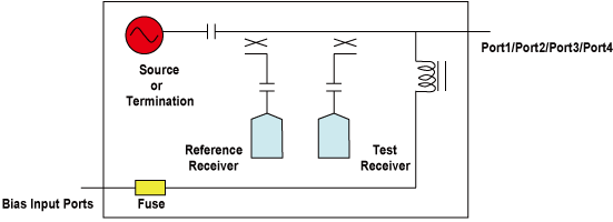
Connect your DC Power Supply to apply Bias Input to the VNA ports through the BNC connectors.
Caution: Do not apply DC voltage exceeding 35 volt.
|
Specification |
Description |
|
Fuse Rating |
0.5A/125V |
|
Part Number |
2110-1439 |
The bias fuses are rated for 0.5A. You are responsible to ensure that devices connected to the test port do NOT draw more current than 0.5A. This will occur, for example, if a calibration SHORT is connected to the test port with bias power ON.
The VNA will meet all of its RF specifications with bias up to 200 mA. As the DC bias is increased, corrected source match and directivity will degrade at low RF frequencies.