Handler IO Tab
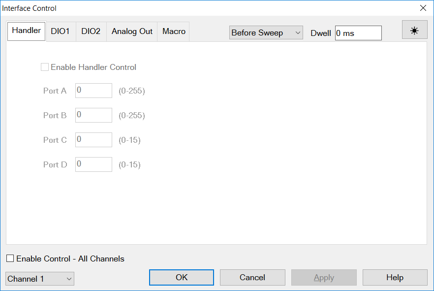
Enable Handler Control Enables and disables sending data out the Handler IO Connector (ENA). The enable is set independently per-channel and for "Before Sweep" and "After Sweep".
Ports A, B, C, D Sends values to the respective Handler I/O port. Although ports C and D are normally bidirectional, ONLY Output mode is allowed using the Interface Control feature. It cannot read from these, or any other, ports.
Enable Control-All Channels Enables and disables ALL Interface Control communication. When cleared (default setting) Interface Control is disabled and NO data is sent. To send data, the individual interfaces must also be enabled.
Channel Pulldown This allows user to set IO independently for each channel.
Before Sweep/After Sweep Pull down Allows setting IO data independently for before or after sweep. Default setting is Before sweep. Before sweep is used to set up command before making a measurement. After Sweep is used to return VNA to a safe state so that the next channel does not have any problems.
Dwell Entry Delay time between all commands sent and measurement start. Set independently per channel and for forward and reverse sweep, not set per IO type. This is used to allow all external devices to settle before making a measurement.
For save or recall, refer to Instrument State Save.
DIO1/ DIO2 Tabs (Device Test I/O)
 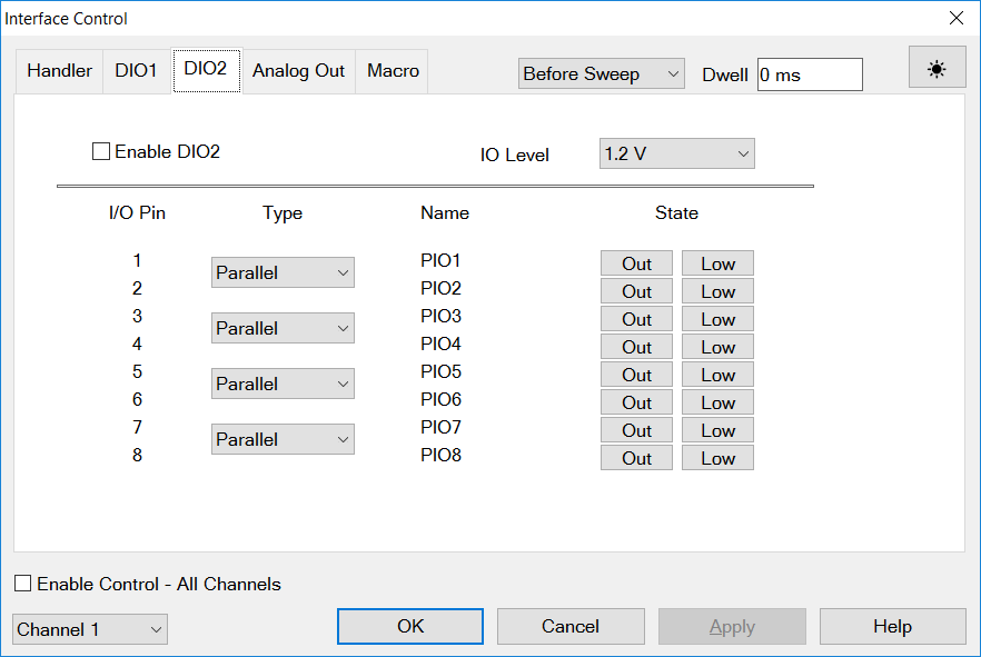
Digital 16-bit IO is composed of 2 independent sets of Digital 8-bit IO. See the Device Test IO in Rear Panel I/O.
The DUT Control function provides 2 different type of controls for user DUT. These are “parallel IO control” and “MIPI RFFE control”. E5080B can provide 2 sets of 8-bitit digital IO. A 8-bit digital IO has up to 8-line parallel IOs, and up to 4 MIPI RFFE controllers, and user can set mixed configuration of parallel IO and MIPI RFFE with some limitations.
The DUT Control signal generation timing is basically same as Control Lines control of External Testset, so the function design is based on the External Testset control.
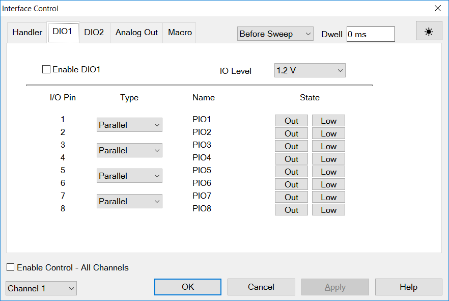
Enable DIO1/DIO2 Enables and disables sending data out the 8-bit digital IO (Device Test I/O).
IO Level Set voltage level of "Power Output" pin of the 8-bit IO. The power out pin is used as VIO of RFEE. This level determine the "HIGH" logic level of all IO pins of the 8-bit IO. The value range is 0.9V to 3.5V with 0.05V resolution.
Type Eight IO pins are consists of 4 group of 2-pins pair: (Pins No. 1 and 2), (Pins No. 3 and 4), (Pins No. 5 and 6), (Pins No. 7 and 8). Each group can be assigned with Parallel or RFFE by using the pull-down box.
Name The name of assigned signal.
State Control buttons are displayed depending on Type selection, either Parallel or RFFE.
-
When Parallel is selected:
-
In or OUT - Select the pin function from Input or Output.
-
Low or High - For input pin, show the current state. For output pin, select the level from Low or High
-
When RFFE is selected:
-
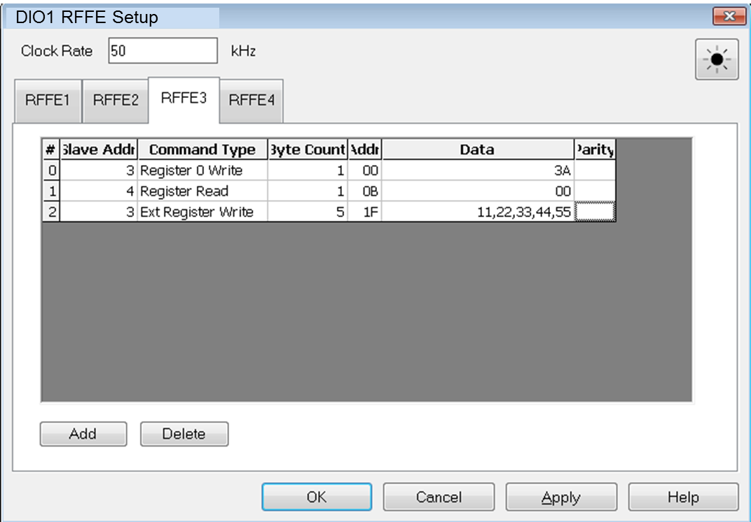
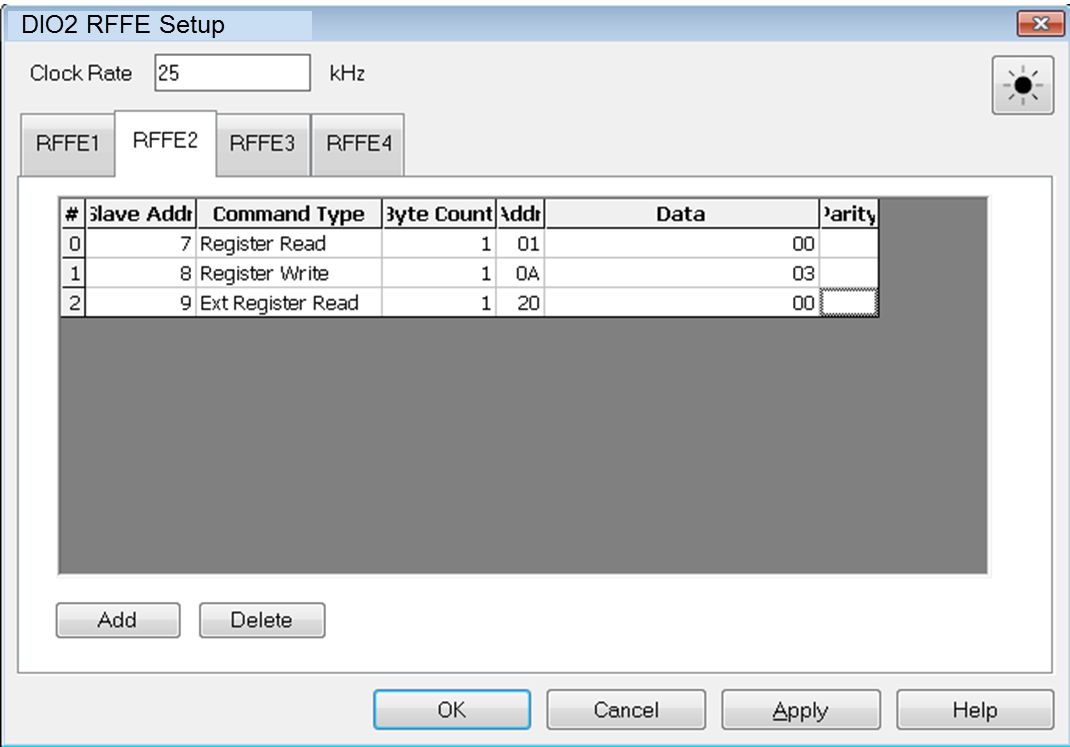
Clicking RFFE setup.. shows the RFFE setup dialog box.
Warning: Users can save or recall IO settings as a state file. So users need to take care not to damage the DUT if they use state files.
Analog Out Tab
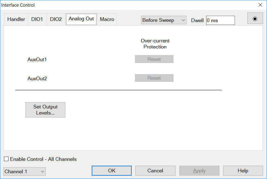
Set Output Levels Clicks on this button will open the DC source dialog to define the DC Source.
Over-current Protection Indicates whether protection has been tripped. Readout will shows the status of signal output, Output On or Output Off.
Reset Resets the protection circuit for the aux port.
App IO Tab
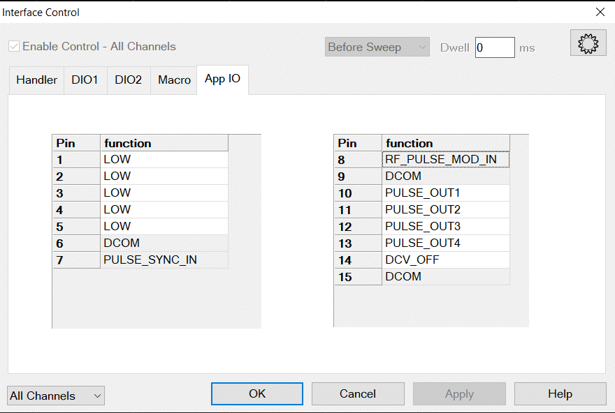
Enable Control-All Channels, Before Sweep, Dwell These controls are disabled.
Function When a white cell is clicked, a drop down list appears to show functions assignable to the specified port. Refer to the command description about “:CONTrol:SIGNal:AIO:PIN<pin>:FUNCtion <func>” for the assignable functions. If “CHANNEL_CTRL” is specified, different functions can be assigned per channel.
All Channels When a channel is selected in the channel scope dropdown, the dialog switches to channel mode as shown in the figure below. Functions can be assigned to the ports for which “CHANNEL_CTRL” has been specified in the global mode.

Function When a white cell is clicked, a drop down list appears to show functions assignable to the specified port. Refer to the command description about “:CONTrol:SIGNal:AIO:PIN<pin>:FUNCtion <func>” for the assignable functions.
Note: Pulse related signals are assigned to same pin# as “PULSE IO” on PNA rear panel.
Dwell After Command Specifies a wait time, in milliseconds, after all commands to all interfaces are sent. Any positive integer is allowed. This is used to allow all external devices to settle before beginning a measurement. An erratic trace could indicate that more settling time is necessary.
Reset All Sets ALL fields on ALL channels to their default values.
Save and Recall Saves and recalls the contents of this dialog box. If the Interface Control dialog box is populated with settings during an Instrument State Save, the settings are automatically recalled with the Instrument State settings.
Interface control uses an *.xml file type. An example file is stored on the VNA hard drive. You can recall it into the dialog, or you can open and edit it with a word processor, such as Word Pad.
OK Applies the settings and closes the dialog box.
Cancel Does not apply changes that were made, and closes the dialog box.
|


