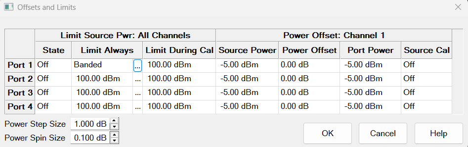
Click a WHITE cell to change values. Shaded cells can NOT be changed.
Remote commands can be sent to lock and unlock the dialog box (UI) settings.
Limit Source Power
Limits the source power at each test port for ALL channels. Use this feature to protect DUTs that are sensitive to overpowering at the input. Source Power levels that exceed the Limit at the specified port are clipped at the limit, the power level in the Source Power column turns red, and an error message is displayed on the screen.
The Power Limit settings and PLimit status indicator survive Instrument Preset. When an Instrument State is recalled, the current Power Limit settings are applied to the recalled state.
To learn more, see Power Limit Overview (scroll up).
State
-
ON - Power is limited to the adjacent value at the specified source port and displays PLimit in the status bar indicating that a power limit is ON.
-
OFF - Power is NOT limited to this value, but to the maximum power of the source.
Limit Always - Limit the source power at all times.
![]() icon - Click to open the Banded Power Limit dialog.
icon - Click to open the Banded Power Limit dialog.
If Banded Power Limits are disabled for the cell, then the cell will display a fixed limit value with default value 100 dBm. Click on the cell to change the value.
If Banded Power Limits are enabled, then the cell will display the text "Banded" and clicking on the cell will do nothing.
Limit During Cal - Limit the source power during calibration.
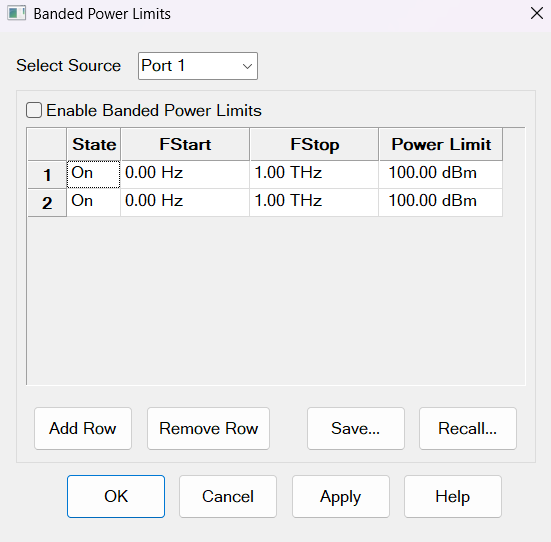
Banded Power Limit
Notes: Each source has an independent set of bands, states, frequencies and power limits.
Select Source Selects a source from the combo box. The default selection is the source which was chosen in the Offsets and Limits dialog. The Band Limits table is used to define the limits of the selected source.
Changing to another source will display the Enable Banded Power Limits checkbox and Band Limits table for that source. User can make changes to those values.
Not all External Source drivers are supported by the Power Limit feature. In particular, very old source drives with an "AG" prefix are not supported and limits cannot be set.
Enable Banded Power Limits When enabled, the limits will be applied to the selected source. Default is disabled.
"Row Number" of the table Each row has a number from 1 to N which is used to label the data in the saved file.
State Click to toggle between two states, On or Off of the band. Default is "On".
FStart, FStop Define the start and stop frequencies of the band. Default values are FStart = 0 Hz and FStop = 1 THz and the range is 0 Hz to 100 THz.
Power Limit Enter the power limit value for each band by clicking on the cell. Default value is +100 dBm and the range is +/- 200 dBm with 0.01dB resolution.
Add Row Click to add a row below the last row.
Remove Row Click to remove the bottow row.
Save... Navigate to the directory where you want to save the Band Limits table for the selected source. The file data includes: State, Fstart, Fstop and Limit. It does not include "Select Source" and " Enable Banded Power Limits". User can copy tables between sources by saving table, changing the selected source, and then recalling the table. The file type is .csv.
Recall Navigate to the directory to recall a Band Limits table for the selected source.
Recall error will be shown if the selected recall file (.csv) is improperly formatted or contains invalid information. Errors found in the file will be listed in the error dialog.
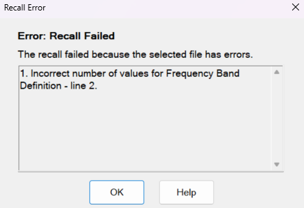
OK Click will close the error dialog and data in the Band Limits table will remain unchanged.
OK Apply the added values in the Banded Power Limit table and close the dialog.
Cancel Close the dialog without saving the added values.
Apply Apply the Enable Banded Power Limits checkbox setting, frequencies and powers. If the values are changed for more than one source by using the Select Source combo box, then all new values for all sources will be applied.
Power Table Logic
-
The table displays one row by default.
-
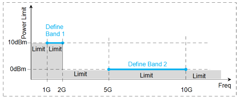
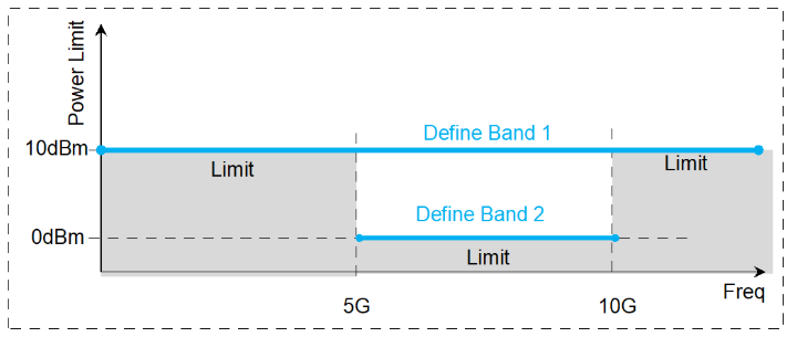
Band Overlap: If frequency bands overlap each other, then the minimum power limit will be applied in the overlap region.
-
Band Gaps: If there are frequency bands not described in the band table, then the defined bands will be extrapolated (with a constant flat value) to create limits where none were defined. The minimum power limit between the two adjacent bands will be used.
Example 1 (Band Gaps):
-
Set Band 1 PLimit = 10 dBm for 1 GHz to 2 GHz
-
Set Band 2 PLimit = 0 dBm for 5 GHz to 10 GHz
Example 2 (Band Overlap):
-
Set Band 1 PLimit = 10 dBm for 0 GHz to 1 THz
-
Set Band 2 PLimit = 0 dBm for 5 GHz to 10 GHz
Power Offset
Power Offset provides a method of compensating port power for added attenuation or amplification in the source path. The result is that power at the specified port, all dialogs, and annotation reflects the added components.
-
For amplification, use positive offset.
-
For attenuation, use negative offset.
Optionally change the Source Power or Port Power values so that the following equation reflects your requirement:
Source Power + Power Offset = Port Power
Source Cal ON / OFF
Notes
-
Power Offset can be used with Power Sweeps. When a power sweep is enabled, the Start and Stop power levels are reported in this dialog.
-
When port power offsets are used, port powers are automatically uncoupled. Port powers may not be coupled again until all port offsets are zero.
-
Cal All does not automatically use the specified power offset during a calibration. To use a power offset for one or more ports when performing a Cal All, you must set the power offset value in the Cal All wizard.
Power Step Size: Specify the arrow key up/down step resolution. The setting is kept even after preset and power off/on.
Power Spin Size: Specify the rotary Knob spin resolution. The setting is kept even after preset and power off/on.
OK Closes the dialog box.