Last Updated: August 29, 2007
This topic provides steps that allow you to start using the test set as quickly as possible. These steps typically use the test set's default configuration to ensure that this process is uncomplicated.
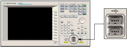
It is recommended that during initial test set configuration, you should connect a USB mouse and keyboard to the test set's USB-A connectors on the test set's front or rear panel. This makes it easier to perform the initial setup tasks. If you require more details about using the test set with or, without a mouse and keyboard, see Using the Test Set with a Mouse and Keyboard or Using the Test Set without a Mouse and Keyboard.
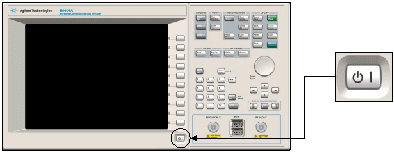
Use the power key to turn on the test set. The green indicator light illuminates.
If this is first time that the test set has been turned on since it was unpacked, the Windows XP Setup Wizard runs.
|
|
You must not turn off the test set or remove power before the Windows XP Setup Wizard completes and the system restarts. If you do, the test set's system software is corrupted and the E6601A WCTS program does not operate correctly. |
The Windows XP Setup Wizard is used to complete the installation and configuration of the Windows XP environment. You must accept the terms of the End-User License Agreement, set the correct date and time, and step through the remainder of the Windows XP Setup Wizard screens to complete the setup of the test set's operating system. Near the end of the Windows setup, the test set is restarted. You do not need to make any selections during the start-up process as the test set is configured for the General Purpose application to start automatically. If you require more details on the Windows XP Setup Wizard, see Using the Windows XP Setup Wizard.
|
|
When the test set is first turned On, the Administrator account is the one that you use by default to log on to Windows XP. The initial password set for this account is “agilent4u”. |
When the General Purpose Application automatically launches you may see one of two messages requesting you to perform an Alignment. You may either be requested to perform an RF Generator Alignment or a Full Alignment.
|
|
If at this stage in using the test set you are not concerned with the measurement accuracy you can leave the alignment to a later time and go directly to Connecting a Wireless Device and Supplying a Suitable Test Mode Signal. |
If you are requested to perform:
an RF Generator Alignment; to ensure accurate measurement results, you must allow the test set 30 minutes to warm up before performing this alignment.
a Full Alignment; to ensure the best measurement performance, you must allow the test set 48 hours to warm up before performing this alignment. This alignment can be performed after a 30 minutes warm up, however the RF Generator level accuracy is reduced by 0.1 dB.
To perform either alignment:
The alignment is done in the System Tools Application. To switch from the General Purpose Application into the System Tools Application use the following procedure:
On the front panel, under SCREENS, press the Config key. The Configuration screen is displayed.
Select the Application Switch softkey. The Application Switch window is displayed.
Set the Selected Application to System Tools, then press Switch Application. The System Tools Application Main screen is displayed.
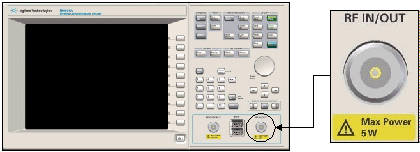
Ensure that no power is present at the front panel RF connectors and remove any cables or connectors from the RF IN/OUT and RF OUT ONLY connectors. If you are operating in a high RF environment, it is recommended that you also terminate the RF connectors with a 50 Ω load.
Press the Alignment softkey.
Set the required Alignment Type then press Run.
Once the alignment is complete you can switch back to the General Purpose Application using the same procedure as you used to switch into the System Tools Application which is detailed above in Step 1.
If you require more information on alignments refer to Alignment Overview.
Connect your wireless device to the RF IN/OUT Type-N connector on the test set's front panel.
You must configure your wireless device to provide a suitable test mode signal for the test set to measure. This configuration is specific to your wireless device.
The application starts with the Main screen displayed and the RF Control window selected.
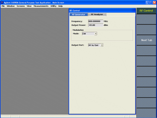
Configure the required parameters in the RF Control window, by clicking the RF Generator and RF Analyzer tabs to set the parameters you want. Set these parameters to values that suit your wireless device and its test mode signal that you want to measure.
You are now ready to make your first measurement.
Press the Meas Select key to display the Measurement Selection window.
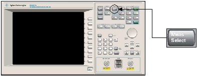
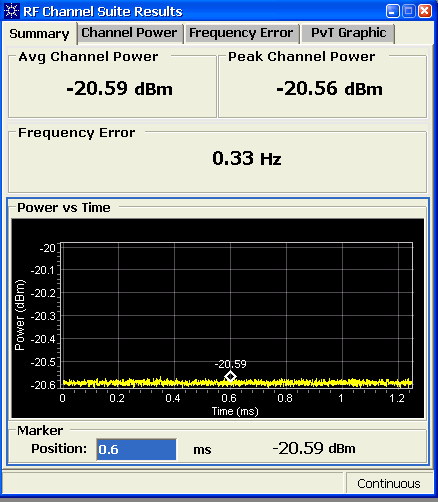
Select RF Channel Suite. The RF Channel Measurement Suite starts and the RF Channel Suite (RFCH) window appears with the Summary tab displayed.
Close the Measurement Selection window.
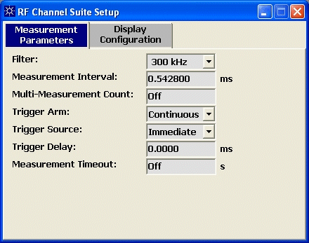
If you want to change any of the setup parameters associated with this measurement suite, press the RF Channel Setup softkey to open the RF Channel Suite Setup window.
You have now performed your first measurement using the test set's front panel. If you want to start other measurements, press the Meas Select key, and in the Measurement Selection window, select the measurement, or measurements you want. To close a measurement clear the measurement in the Measurement Selection window.

