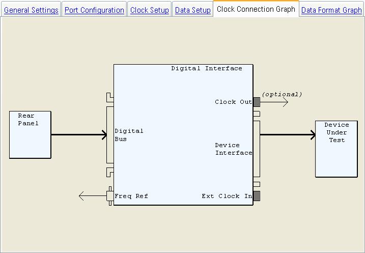
This illustration shows the N5102A digital signal interface module setup and signal flow. The illustration is dynamic because it changes based on the selections made in the software's user interface.
The software selections that affect the illustration are:
The location of the external
device that the N5102A module is assigned. The N5102A module can be assigned
as an output device from the N5106A. or as an input
device to the N5106A.This choices changes the signal flow path between
the Rear Panel, the N5102A, and the Device Under Test is displayed as
shown.  Illustration…
On the Clock Setup tab, the Frequency Reference Source
can be changed between Internal and External. If External is selected,
a block is displayed with the label "Frequency Reference Source"
and the arrow representing signal path direction is changed with respect
to the Freq Ref connector on the N5102A module. Illustration…
On the Clock Setup tab, the Clock Source can be changed
between Internal, External, and Device. If External is selected, a block
is displayed with the label "External Clock Source" and the
arrow representing signal path direction of the external clock source.
If Device is selected, an arrow representing signal path direction of
the clock source and labeled "Device Clock" is displayed. Illustration…
General Settings
Port Configuration
Clock Setup
Data Setup
Data Format Graph