Range: 1 kHz to 150 MHz
Default: 100 MHz
Resolution: 1 Hz
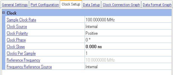
Choices: Internal, External, Device
Default: Internal
Selects one of three possible clock sources. When this value is changed, the Clock Connection Graph is updated to reflect the changed value.
|
Internal |
With this choice, the N5102A module generates the sample clock. When the clock source is internal, both Reference Frequency and Frequency Reference Source become active. |
|
External |
With this choice, the N5102A module uses a clock provided by an external source through the Ext Clock In connector. The external clock is also available to the DUT at the Ext Clock Out connector. |
|
Device |
With this choice, the DUT provides the clock to the N5102A module through a pin on the breakout board connector ribbon cable. See the N5102A Digital Signal Interface Module Installation Guide for information about breakout boards. |
Choices: Negative, Positive
Default: Positive
Selects which clock edge (rising or falling) is aligned with the start of a sample for a parallel or parallel interleaved data transmission, and with the start of each bit for a serial data transmission. When this value is changed, the Data Format Graph is updated to reflect the changed value. Refer to Digital Signals for examples of this change.
|
Positive |
This choice sets the sample alignment to occur on the rising edge transition of the clock signal. |
|
Negative |
This choice sets sample alignment to occur on the falling edge transition of the clock signal. The Negative selection functions the same as setting the clock phase to 180 degrees. |
This selection may be changed even while the waveform is playing.
Choices: 0°, 90°, 180°, 270°
Default: 0°
Adjusts the clock phase in 90-degree increments to 0, 90, 180, or 270 degrees. When this value is changed, the Data Format Graph is updated to reflect the changed value. Refer to Digital Signals for examples of this change.
This selection may be changed even while the waveform is playing.
Range: –4.961 ns to 4.961 ns
Default: 0 ns
Resolution: 1 ps
Provides a fine-adjustment for aligning the clock to the valid portion of the data. Because this is a fine adjustment, it provides greater benefit at higher clock rates. The maximum range for this value is +/- 5 nS, but the actual range depends on the clock rate. The clock skew value is rounded to a resolution of 1/sample rate and is only active when the clock rate is greater than 25 MHz. If the sample rate is changed, the clock skew will adjust based on the previous number of samples skewed. When this value is changed, the Data Format Graph is updated to reflect the changed value. Refer to Digital Signals for examples of this change.
This setting may be changed even while the waveform is playing.
Choices: 1, 2, 4
Default: 1
Dependency: Displayed only when DSIM is configured as an output and available
only when Port Configuration is set to Parallel
Sets the number of clock cycles per sample output by the N5102A module. When you select a number of clocks per sample that is greater than one, the sample is held for the selected number of clock cycles. This reduces the sample rate relative to the input clock rate by a factor equal to the clocks per sample value. When this value is changed, the Data Format Graph is updated to reflect the changed value. Refer to Digital Signals for examples of this change.
Range: 1 MHz to 100
MHz
Default: 10 MHz
Resolution: 0.1 Hz
Dependency: Available when Clock Source is set to Internal and Reference
Frequency Source is set to External
Sets the frequency of the reference used to generate the N5102A module internal clock. When Reference Frequency Source is set to Internal, the Reference Setting value is set to 10 MHz and is disabled.
Choices: Internal, External
Default: Internal
Selects the source of the reference source. When this value is changed, the Clock Connection Graph is updated to reflect the changed value.
|
Internal |
This setting configures the N5102A module to use an internal 10 MHz reference. |
|
External |
This setting configures the N5102A module to use an external reference frequency source provided by an external source through the N5106A rear-panel Ext Clock In connector. The external reference frequency source is also available to the DUT at the Ext Clock Out connector. |
General Settings
Port Configuration
Data Setup
Clock Connection Graph
Data Format Graph